Table of Contents
Advertisement
Quick Links
201 Daktronics Drive PO Box 5128 Brookings, SD 57006
tel 800-325-8766 fax 605-697-4700
www.daktronics.com
RTX-1100/1800 Gen 1 Series
DAKT-0200-04
Display Manual
DD2790470
Customer: ______________________
Contract: _______________________
Model Number: _________________
Serial Number: __________________
Activation Date: _________________
Rev 1—17 August 2015
Advertisement
Table of Contents
Troubleshooting

Related Manuals for Daktronics RTX-1100 Gen 1 Series


Summary of Contents for Daktronics RTX-1100 Gen 1 Series
- Page 1 RTX-1100/1800 Gen 1 Series DAKT-0200-04 Display Manual DD2790470 Rev 1—17 August 2015 Customer: ______________________ Contract: _______________________ Model Number: _________________ Serial Number: __________________ Activation Date: _________________ 201 Daktronics Drive PO Box 5128 Brookings, SD 57006 tel 800-325-8766 fax 605-697-4700 www.daktronics.com...
- Page 2 No part of this book covered by the copyrights hereon may be reproduced or copied in any form or by any means—graphic, electronic, or mechanical, including photocopying, taping, or information storage, and retrieval systems—without written permission of the publisher. Daktronics is a registered trademark of Daktronics, Inc. All other trademarks are property of their respective companies.
-
Page 3: Table Of Contents
Table of Contents Section 1: How to Use This Manual ........................1 Resources ................................1 Numbering Conventions............................. 1 Part Number ..............................1 Module Number ............................2 Section Number ............................. 2 Model Number .............................. 2 Important Safeguards ............................3 Section 2: Mechanical Installation ........................ - Page 4 Troubleshooting ..............................31 Section 5: Replacement Parts ..........................33 Replacement Parts List ............................33 Daktronics Exchange and Repair & Return Programs ................. 33 Exchange Program ............................33 Before Contacting Daktronics ........................33 Repair & Return Program .......................... 34 Shipping Address............................34 Daktronics Warranty &...
-
Page 5: How To Use This Manual
Layout; Comp & Pwr, RTX-1XY0 ...................Drawing B-1160703 Daktronics identifies manuals by the DD number located on the cover page of each manual. For example, this manual would be referred to as DD2790470. Please list the model number, display serial number, and the date this display became operational in the blanks provided on the front page of this manual. -
Page 6: Module Number
Module Number Figure 3 illustrates how Daktronics numbers modules on a ribbon display. A101 A105 A102 A103 A104 A201 A202 A205 A203 A204 A301 A303 A304 A302 A305 Figure 3: Module Number (Front View/Display Face) Section Number Figure 4 illustrates how Daktronics numbers sections on a ribbon display. -
Page 7: Important Safeguards
Important Safeguards • Please read and understand the installation instructions before beginning the installation process. • Do not drop the control equipment or allow it to get wet. • Do not disassemble the control equipment or electronic controls of the display; failure to follow this safeguard will make the warranty null and void. -
Page 9: Mechanical Installation
The installer is responsible for ensuring the mounting structure and hardware are built per the stamped engineering drawings and are capable of supporting the display. Daktronics is not responsible for display mounting decisions made by others. -
Page 10: Display Preparation
Display or Display Section Lifting Single Section Daktronics equips each section with two lift lugs for lifting the sections into position. To expose these lift lugs, use the -inch hex security bit (Daktronics part number TH-1170) supplied in the toolkit to release all beverage shroud latches and open the beverage shroud. -
Page 11: Weight Approximations
The beverage shrouds should be removed prior to lifting the sections to prevent damage to the shrouding. Lifting bar The lift lugs should be located one to two module lifting bar widths inward, depending on the section size, from Eyebolt strength each end of the section. - Page 12 RTX-1100-16MT RTX-1100-20MT Section Size Section Size Section Weight (pounds) Section Weight (pounds) (millimeters – pixels) (millimeters – pixels) 810x1100 – 44x66 810x1100 – 36x54 810x1475 – 44x88 810x1475 – 36x72 810x1850 – 44x110 810x1850 – 36x90 810x2225 – 44x132 810x2225 – 36x108 810x2600 –...
-
Page 13: Display Mounting
RTX-1800-10MN RTX-1800-15MN Section Size Section Size Section Weight (pounds) Section Weight (pounds) (millimeters – pixels) (millimeters – pixels) 1180x2975 – 108x288 1180x2975 – 72x192 1550x1100 – 144x108 1550x1100 – 96x72 1550x1475 – 144x144 1550x1475 – 96x96 1550x1850 – 144x180 1550x1850 – 96x120 1550x2225 –... - Page 14 Verify all rear section clips are securely attached from the factory before lifting each section. In most cases, each section should have two rear section clip locations. These clips should align with the pre-installed wall clips on the structure. Refer to Figure 11 and Figure 12. Note: Some cabinet clip adjustment may be necessary.
- Page 15 Use a -inch hex T-handle (Daktronics part number TH-1088) to rotate the upper latch clockwise and the lower latch counterclockwise. Refer to Figure 14 and Figure 15. Access the latches by removing the modules or the module pan entirely.
-
Page 16: Corner Or Gap Mounting
Locate the transition caps with pass-through holes Conduit clip and use the supplied #10 self-tapping screws (Daktronics part number HC-1151) to attach them to the sections on either side of the gap. Transition cap Remove the two-inch flexible conduit pieces... -
Page 17: Wing Section Installation
Ensure the second section is vertically plumb and horizontally aligned with the previous section before attaching to the wall. Begin pressing the flex conduit through the second section’s pass-through hole once the second section is close enough. Ensure at least 2" of conduit extends into both sections. Trim any excess conduit from the inside of the section. -
Page 18: Border Attachment
#10 screw @ 6 (typical) Cap: Use a -inch nutdriver (Daktronics part number TH-1156) to secure the #10 self-tapping screws (HC-1151) at a quantity of six and attach the caps. Refer to Figure 30. Figure 30: Attaching Cap... - Page 19 Clean-look border: Use a -inch nutdriver (TH-1156) to secure the #6 nuts (HC-1238) at a quantity of six and attach the borders. Refer to Figure 31. #6 Nut @ #10 Screw 6 (typical) @ 6 (typical) Flange border Spacer Clean-look Spacer border Figure 31: Attaching Clean-Look Border...
-
Page 21: Electrical Installation
Electrical Code and/or other applicable local codes. This includes proper grounding and bonding of the sign. This display is suitable for wet locations. Daktronics engineering staff must approve any changes that may affect the weather tightness of the display. If any modifications are made to the weather tightness of the display, detailed drawings of the changes must be submitted to Daktronics engineering staff for evaluation and approval, or the warranty will be null and void. -
Page 22: Common Connectors
These connectors are not found in every display. Water-Tight SATA Cable Connector Daktronics uses a wide variety of SATA cables and SATA cable connectors. Figure 34 illustrates one of the most commonly used SATA cable connectors. To... -
Page 23: Control Cable
The material of an earth-ground electrode differs from region to region and varies with conditions present at the site. Consult local grounding codes. Daktronics does not recommend using the support structure as an earth-ground electrode; concrete, primer, corrosion, and other factors make the support structure a poor ground. -
Page 24: Three-Phase Installation
If power goes left, install power whip harness (Daktronics part number W-2683) if not already installed Figure 36: Power Installation Main Disconnect Refer to the contract-specific System Riser Diagram to determine who must supply a fused main distribution/disconnect, surge suppressor, and the necessary wiring for power distribution to multiple display termination panels. -
Page 25: Display Wiring
When terminating power at the termination panel, the individual power phases must balance as evenly as possible. Current draw per line, as noted on the contract-specific System Riser Diagram, is stated as the high leg current draw. Refer to the Power Entrance Drawings in Appendix A for power termination information. Display Wiring Reference Documents: RTX-1XY0 SATA Routing Options .................Drawing B-1160835... -
Page 26: Signal Redundancy
Signal Redundancy Reference Documents: VIP-4060 Operator’s Manual ...................... DD1804047 IDM User Manual ........................DD2097912 Config Drawing .........................Contract-Specific Full-Data Redundancy Full-data redundancy provides primary and redundant video image processors (VIPs), PLRs, and SATA connections throughout the entire display to protect the system from signal failure. If any signal component, cabling, or connection fails, its counterpart takes over and limits the signal failure to as little of the display as Power... -
Page 27: Maintenance & Troubleshooting
Removes RTX-1800 modules These tools are found in the toolkit (Daktronics part number 0A-1755-0001). Toolkits include other items not on this list and additional replacement tools may be ordered directly from Daktronics; refer to Section 5.2. Display Access RTX displays are designed for either front or top access, depending on site requirements and customer preference. -
Page 28: Service & Diagnostics
Top-access displays allow a technician to access internal components from a platform on the rear of the section at the top of the display. The module pans slide vertically out of position, allowing access into the sections. Refer to Figure 39 and Figure 40. Module pan slides up Figure 39: Removing Front Modules... -
Page 29: Module Pan
1. Disconnect power to the display. 2. Use a -inch hex security bit (Daktronics part number TH-1170) to release the beverage shroud security latches. The beverage shroud may be left on in a flipped-up position or removed by rotating it up and unhooking the spring-loaded hinge pins. Refer to Figure 45 and Figure 46. - Page 30 Clip one end of the module pan safety lanyard to the closest lift lug in the top perimeter and clip the other end into the handle of the module pan in need of service. Refer to Figure 47 and Figure 48. Figure 47: Lift Lug Figure 48: Module Pan Handle Disconnect all SATA and power cables from the top of the module pan handle after the lanyard is...
-
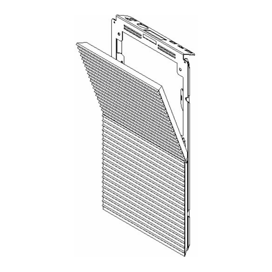
Page 31: Module
Module RTX-1100 Figure 51, Figure 52, and Figure 53 show front and rear views of a module. Figure 53: Module Rear Figure 51: Module Front Figure 52: Module Front (RTX-1100HD) (RTX-1100MT) Refer to Figure 55 while following the steps below. 1. -
Page 32: Rtx-1800
Attach one end of a safety lanyard to the rings on either the top or bottom of the module and the other end to a secure location within the display to prevent the module from falling if dropped. Disconnect the power and signal cables from the rear of the module. Reverse these steps to install a module in a display. - Page 33 1. Disconnect power to the display. 2. Access the module. Front access: Position the module access tool (Daktronics part number TH-1212) so the arrows on the handle are pointing up. Use slight thumb pressure to insert the tool into the module until it clicks.
-
Page 34: Prolink Router
ProLink Router Disconnect power to the display. Remove Use a -inch hex security bit (Daktronics part with Phillips Hinge screwdriver number TH-1170) to release the beverage shroud security latches. The beverage shroud may be left on in a flipped-up position or removed by rotating it up and unhooking the spring-loaded hinge pins. -
Page 35: Prolink Router
ProLink Router Figure 65 illustrates a ProLink router (PLR). A PLR is a display interface board that passes display data from the ProLink6 control system modules and other PLRs. Refer to the DD1735784 ProLink Router 6X5X Installation & Maintenance Manual for further information. - Page 36 Display Problem Troubleshooting Steps • Ensure the display is receiving power and all breakers are turned on. When power is applied to the display, power supply LEDs should turn on. Entire display is blank. • Ensure the video image processor (VIP) is not blank. •...
-
Page 37: Replacement Parts
& return program. Exchange Program Daktronics unique Exchange Program is a quick service for replacing key parts in need of repair. If a part requires repair or replacement, Daktronics sends the customer a replacement, and the customer sends the defective part to Daktronics. This decreases display downtime. -
Page 38: Repair & Return Program
Repair & Return Program For items not subject to exchange, Daktronics offers a Repair & Return Program. To send a part for repair, follow these steps: Call or fax Daktronics Customer Service. - Page 39 Glossary Lanyard Attachment Ring: a ring found on the back of each module. The lanyard attaches to the ring to keep the module from falling to the ground. Latch Release: a device that holds the module firmly to the display frame. There are two per module, one on the top and one on the bottom.
-
Page 41: Appendix A: Drawings
Appendix A: Drawings Refer to Section 1.1 for information regarding how to read the drawing number. These drawings offer general information pertaining to most RTX displays and are listed in alphanumeric order. Any contract-specific drawings take precedence over the general drawings. Layout;... -
Page 43: Appendix B: Supplementary Documents
THE CONCEPTS EXPRESSED AND DETAILS SHOWN ON THIS DRAWING ARE CONFIDENTIAL AND PROPRIETARY. DO NOT REPRODUCE BY ANY MEANS WITHOUT THE BROOKINGS, SD 57006 EXPRESS WRITTEN CONSENT OF DAKTRONICS, INC. COPYRIGHT 2014 DAKTRONICS, INC. DO NOT SCALE DRAWING RTX-1XY0 PROJ: REMOVED NOTES FOR REDUNDANT POWER LOCATIONS LAYOUT;... - Page 44 IT IS THE RESPONSIBILITY OF THE ELECTRICAL INSTALLATION CONTRACTOR TO ENSURE THAT ALL ELECTRICAL WORK PERFORMED ON SITE MEETS OR EXCEEDS ALL LOCAL & NATIONAL ELECTRIC CODES FOR WIRING AND SPECIFICATIONS. THESE ARE ALSO REFERENCED ON CONTRACT SPECIFIC RISER DIAGRAMS FIELD TERMINATE AT THESE LOCATIONS OR ANY CORRESPONDING OPEN LOCATIONS FOR EASE OF TERMINATION...
- Page 47 DO NOT REPRODUCE BY ANY MEANS WITHOUT THE BROOKINGS, SD 57006 ATTACH FANS TO BOTTOM PLATE OF CABINET EXPRESS WRITTEN CONSENT OF DAKTRONICS, INC. CHANGED BUS HARN BOX & TP BOX TO USE HC-1554 COPYRIGHT 2014 DAKTRONICS, INC. DO NOT SCALE DRAWING...
- Page 48 DAKTRONICS, INC. THE CONCEPTS EXPRESSED AND DETAILS SHOWN ON THIS DRAWING ARE CONFIDENTIAL AND PROPRIETARY. DO NOT REPRODUCE BY ANY MEANS WITHOUT THE EXPRESSED WRITTEN CONSENT OF DAKTRONICS, INC. COPYRIGHT 2014 DAKTRONICS, INC. RTX-1XY0 ADDED 2 & 3-PIN DETAILS DATE: ADDED MALE/FEMALE DETAIL TO WING SATA DETAIL BLOCK DIAGRAM;...
- Page 49 THE CONCEPTS EXPRESSED AND DETAILS SHOWN ON THIS DRAWING ARE CONFIDENTIAL AND PROPRIETARY. DO NOT REPRODUCE BY ANY MEANS WITHOUT THE EXPRESSED WRITTEN CONSENT OF DAKTRONICS, INC. ADDED 2 & 3-PIN DETAILS DATE: ADDED MALE/FEMALE DETAIL TO WING SATA DETAIL COPYRIGHT 2014 DAKTRONICS, INC.
- Page 50 DAKTRONICS, INC. THE CONCEPTS EXPRESSED AND DETAILS SHOWN ON THIS DRAWING ARE CONFIDENTIAL AND PROPRIETARY. DO NOT REPRODUCE BY ANY MEANS WITHOUT THE EXPRESSED WRITTEN CONSENT OF DAKTRONICS, INC. COPYRIGHT 2014 DAKTRONICS, INC. RTX-1XY0 BLOCK DIAGRAM; RTX-1XY0, 4-HIGH ACAMPBE ACAMPBE...
- Page 51 DAKTRONICS, INC. THE CONCEPTS EXPRESSED AND DETAILS SHOWN ON THIS DRAWING ARE CONFIDENTIAL AND PROPRIETARY. DO NOT REPRODUCE BY ANY MEANS WITHOUT THE EXPRESSED WRITTEN CONSENT OF DAKTRONICS, INC. COPYRIGHT 2014 DAKTRONICS, INC. RTX-1XY0 RTX-1XY0 SATA ROUTING OPTIONS ACAMPBE ACAMPBE...
- Page 52 W-1659 @ 1 THIS DRAWING ARE CONFIDENTIAL AND PROPRIETARY. DO NOT REPRODUCE BY ANY MEANS WITHOUT THE BROOKINGS, SD 57006 EXPRESS WRITTEN CONSENT OF DAKTRONICS, INC. ADDED FIBER INTERCONNECT NOTE TO TOP SECTION COPYRIGHT 2014 DAKTRONICS, INC. BOTTOM JACK (J-1435) TO...
- Page 53 DRAWING ARE CONFIDENTIAL AND PROPRIETARY. DO NOT REPRODUCE BY ANY MEANS WITHOUT THE EXPRESS work performed on-site meets or WRITTEN CONSENT OF DAKTRONICS, INC. COPYRIGHT 2014 DAKTRONICS, INC. exceeds all local and national electric RTX-1XY0 codes for wiring and specifcations.
- Page 55 This section includes the following: • DD1402020 Ribbon Board Cabinet Lifting Instructions Quick Guide • DD2725331 RTX-1100/1800 Gen 1 Series Sectional Installation Guide • DD2789237 RTX-1100/1800 Gen 1 Series Power Numbers • ED-14158 Face Cleaning Procedures for Daktronics LED Matrix Displays Supplementary Documents...
- Page 57 Note: Maximum fork center-to-center (c-c) spacing must not exceed 36 inches. Using a forklift for overhead lifting is acceptable only in crane-unloading configurations. Refer to Figure 1. DD1402020 Rev 2 201 Daktronics Dr. P.O. Box 5128 Brookings, SD 57006 12 March 2015 tel: 800-325-8766 fax: 605-697-4700...
- Page 58 Note: Maximum fork center-to-center (c-c) spacing must not exceed 36 inches. Using a forklift for overhead lifting is acceptable only in crane-unloading configurations. Refer to Figure 3. DD1402020 Rev 2 201 Daktronics Dr. P.O. Box 5128 Brookings, SD 57006 12 March 2015 tel: 800-325-8766 fax: 605-697-4700...
- Page 59 Refer to contract-specific Shop Drawing for details. Figure 9: Interconnecting Figure 10: Interconnecting Sections Sections Figure 7: Rear Section Clips DD2725331 Rev 1 201 Daktronics Dr. P.O. Box 5128 Brookings, SD 57006 15 August 2014 tel: 866-343-6018 fax: 605-697-4700 www.daktronics.com...
- Page 60 Repeat Steps 1-5 in Standard Section Installation to continue mounting the section. DD2725331 Rev 1 201 Daktronics Dr. P.O. Box 5128 Brookings, SD 57006 15 August 2014 tel: 866-343-6018 fax: 605-697-4700 www.daktronics.com...
- Page 61 Entrance Diagram, Drawing B-1160858, Cable (power) (power) Sectional and Figure 31. termination panel Coil (fiber) Figure 31: Fiber Patch Panel DD2725331 Rev 1 201 Daktronics Dr. P.O. Box 5128 Brookings, SD 57006 15 August 2014 tel: 866-343-6018 fax: 605-697-4700 www.daktronics.com...
- Page 62 Front access: Position the access tool 2-pin Optional power (Daktronics part number Use a " hex security bit (Daktronics part number TH-1170) to release redundant jack 3-pin power the beverage shroud security latches. The beverage shroud may be left TH-1212) so the arrows on the...
- Page 63 1592 4x5 – 96x120 1512 12.6 4x6 – 112x168 1908 15.9 4x6 – 112x168 1901 4x6 – 96x144 1812 15.1 DD2789237 Rev 0 201 Daktronics Dr. P.O. Box 5128 Brookings, SD 57006 05 May 2014 tel: 866-343-6018 fax: 605-697-4700 www.daktronics.com...
- Page 64 4x5 – 88x110 1596 13.3 4x5 – 88x110 1592 4x6 – 96x144 1806 4x6 – 88x132 1908 15.9 4x6 – 88x132 1901 DD2789237 Rev 0 201 Daktronics Dr. P.O. Box 5128 Brookings, SD 57006 05 May 2014 tel: 866-343-6018 fax: 605-697-4700 www.daktronics.com...
- Page 65 1497 4x5 – 144x180 1500 12.5 4x6 – 72x108 1812 15.1 4x6 – 72x108 1806 4x6 – 144x216 1800 15.0 DD2789237 Rev 0 201 Daktronics Dr. P.O. Box 5128 Brookings, SD 57006 05 May 2014 tel: 866-343-6018 fax: 605-697-4700 www.daktronics.com...
- Page 66 4x5 – 96x120 1512 12.6 4x5 – 96x120 1497 4x6 – 144x216 1806 4x6 – 96x144 1812 15.1 4x6 – 96x144 1806 DD2789237 Rev 0 201 Daktronics Dr. P.O. Box 5128 Brookings, SD 57006 05 May 2014 tel: 866-343-6018 fax: 605-697-4700 www.daktronics.com...
- Page 67 Face Cleaning LED Matrix Displays 1 of 4 This document outlines materials and methods used in cleaning Daktronics LED matrix displays. The procedures apply to all LED matrix screens, including Galaxy , HD-X, ProAd , ProStar , DVX, RTX, DBN, DVN, RTN, DB-4xxx, ®...
- Page 68 Work from top to bottom safely within reach from a lift or a stage. Take care not to damage LEDs or the plastic louvers by catching the cloth on them. ED-14158 Rev 05 201 Daktronics Dr. P.O. Box 5128 Brookings, SD 57006-5128 12 September 2014 tel 605-697-4000 or 800-325-8766 Fax 605-697-4700 www.daktronics.com...
- Page 69 70% alcohol isopropyl rubbing alcohol (Figure 2) • High-performance microfiber cloth (Figure 3) Figure 2: Alcohol Figure 3: Microfiber Cloth ED-14158 Rev 05 201 Daktronics Dr. P.O. Box 5128 Brookings, SD 57006-5128 12 September 2014 tel 605-697-4000 or 800-325-8766 Fax 605-697-4700 www.daktronics.com ® daktronics...
- Page 70 Examine display and touch up areas as needed. Refer to Figure 7. Dirty Clean Module Module Figure 7: Touch Up ED-14158 Rev 05 201 Daktronics Dr. P.O. Box 5128 Brookings, SD 57006-5128 12 September 2014 tel 605-697-4000 or 800-325-8766 Fax 605-697-4700 www.daktronics.com ® daktronics...
-
Page 71: Appendix C: Daktronics Warranty & Limitation Of Liability
Appendix C: Daktronics Warranty & Limitation of Liability This section includes the Daktronics Warranty & Limitation of Liability statement. Daktronics Warranty & Limitation of Liability... - Page 72 ...
- Page 73 DAKTRONICS WARRANTY & LIMITATION OF LIABILITY This Warranty and Limitation of Liability (the “Warranty”) sets forth the warranty provided by Daktronics with respect to the Equipment. By accepting delivery of the Equipment, Purchaser agrees to be bound by and accept these terms and conditions. Unless otherwise defined herein, all terms within the Warranty shall have the same meaning and definition as provided elsewhere in the Agreement.
- Page 74 In no event shall Daktronics be liable to Purchaser or any other party for loss, damage, or injury of any kind or nature arising out of or in connection with this Warranty in excess of the purchase price of the Equipment actually delivered to and paid for by the Purchaser. The Purchaser’s remedy in any dispute under this Warranty shall be ultimately limited to the Purchase Price of the Equipment to the extent the Purchase Price has been paid.
Need help?
Do you have a question about the RTX-1100 Gen 1 Series and is the answer not in the manual?
Questions and answers