
Related Manuals for Daktronics PC-2002


Summary of Contents for Daktronics PC-2002
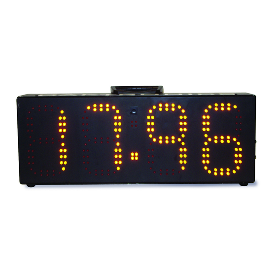
- Page 1 PC-2002 PACE CLOCK SYSTEM DISPLAY MANUAL P1153 ED-14253 Rev 05 13 December 2019 201 Daktronics Drive Brookings, SD 57006-5128 www.daktronics.com/support 800.325.8766...
- Page 2 Daktronics trademarks are property of Daktronics, Inc. All other trademarks are property of their respective companies.
-
Page 3: Table Of Contents
Display Components ..........................12 Replacing the Digit/Driver Printed Circuit Board ................13 Schematics ............................13 Replacement Parts ..........................13 Daktronics Exchange and Repair & Return Programs ����������������������������������������������������14 Exchange Program ..........................14 Repair & Return Program ........................15 Daktronics Warranty & Limitation of Liability ...................15 A Reference Drawings �����������������������������������������������������������������������������������������������������������17 Daktronics Warranty &... - Page 4 This page intentionally left blank.
-
Page 5: Introduction
This manual explains the installation and maintenance of Daktronics PC-2002 pace clock display. For additional information regarding safety, installation, operation, or service, refer to the telephone numbers listed in Section 6: Daktronics Exchange and Repair & Return Programs (p�14). This manual is not specific to a particular installation. Project- specific information takes precedence over general information found in this manual. -
Page 6: Resources
Transformer T-XXXX Metal part 0M-XXXXXXX Fabricated metal assembly 0S-XXXXXX Specially ordered part PR-XXXXX-X Product Safety Approval The PC-2002 is ETL-listed, tested to CSA standards and CE-labeled for indoor use only. Contact Daktronics with any questions regarding the testing procedures. Introduction... -
Page 7: Mechanical Installation
The PC-2002 can mount directly to the wall surface using top and bottom mounting brackets. These brackets then attach to the wall with four anchors. Refer to Figure 4. -
Page 8: Electrical Installation
PC-2002 display. Figure 5: Electrical Installation Note: PC-2002 displays feature an internal time delay 1/2 amp, 250 V fuse for 120 VAC models or 1/4 amp 250 V fuse for 240 VAC models. In the unlikely event the fuse needs to be replaced, contact Daktronics Customer Service. -
Page 9: Wireless Signal Connection
Wireless Signal Connection The PC-2002 is capable of being controlled via wireless signal. The wireless radio system requires a Daktronics All Sport scoring console or OmniSport 2000 timing console ® ® equipped with radio transmitter as well as a radio receiver mounted inside the display. -
Page 10: Radio Settings
For more information about the wireless radio control option, refer to the Gen VI Radio Installation Manual (DD2362277), provided with the receiver unit and available online at www.daktronics.com/manuals. Radio Settings With a radio receiver installed in the display, watch for the radio Broadcast settings (“b1”) and Channel settings (“C1”) during the Power-On Self Test (POST). -
Page 11: Controls & Timing Functions
JC-100 Console Operation Connect the 4-pin power/signal cable from the JC-100 Judges Console to a J-box, and from the J-box to the PC-2002 as shown in DWG-191740. The keypad insert number needed for operation is LL-2584 (DWG-191855). When the PC-2002 is turned on and the JC-100 is connected, press <MENU> on the control console to view the available options. -
Page 12: Time
Time MENU-SETTINGS The Time setting lets operators enter desired timing options 1-TIME for the mode. To change the preset time, press <MENU>, and then press <ENTER>. Press <ENTER>, input the desired time ENTER TIME using the keypad, and then press <ENTER> once more. 00:00 * Note: For 12 Hour Time of Day (mode 5), select whether the time is AM or PM using the arrow keys. -
Page 13: Horn
• SWIM – This step allows operators to enter the amount of time to have the swimmer(s) swim within one step. • REST – This step allows operators to enter the amount of time to have the swimmer(s) rest within one step. •... -
Page 14: Mode #3: Game Clock
The TEAM MANAGER must have the Workout Manager Basic option configured. After creating a workout in the Hy-Tek software: 1� Turn on the PC-2002, connect the JC-100 console, and set to mode 1–WORKOUT. 2� The interface cable (Daktronics part # 0A-1153-0036) has a 9-pin serial connector on one end and a stereo phone jack connector on the other end. - Page 15 7� Click on the Transfer menu in the upper-left corner of the screen. A message should appear that reads “Transfer completed for lanes 1.” Click OK. The PC-2002 should read “donE”. If this does not happen, the download did not work properly.
-
Page 16: Display Maintenance
Disconnect power when not using the display� Display Components The PC-2002 uses a single printed circuit board (PCB) that contains all of the electronics needed to make this system work: digit LEDs, control processors, power input connectors, horn, and other components. All switches, power systems, and input/output terminations are connected to the PCB. -
Page 17: Replacing The Digit/Driver Printed Circuit Board
0P-1153-0005 Surface Mount Hardware 0A-1153-0412 12 V Buzzer DS-1487 Transformer, 120 VAC T-1082 5-pin to 6-pin Radio Adapter W-2913 Refer to Section 6: Daktronics Exchange and Repair & Return Programs (p�14) for information on exchanging or returning parts. Display Maintenance... -
Page 18: Daktronics Exchange And Repair & Return Programs
Fill out and attach the enclosed UPS shipping document. c� Ship the part to Daktronics. 3� The defective or unused parts must be returned to Daktronics within 5 weeks of initial order shipment� If any part is not returned within five (5) weeks, a non-refundable invoice will be presented to the customer for the costs of replenishing the exchange parts inventory with a new part. -
Page 19: Repair & Return Program
Repair & Return Program For items not subject to exchange, Daktronics offers a Repair & Return Program. To send a part for repair, follow these steps: 1� Call or fax Daktronics Customer Service� Refer to the appropriate number in the chart on the previous page. - Page 20 This page intentionally left blank.
-
Page 21: A Reference Drawings
Any contract-specific drawings take precedence over the general drawings. Reference Drawings: Schematic; PC-2002 ................... DWG-187843 Riser Diagram; PC-2002 Permanent Install ............DWG-191740 Insert, LL-2584, JC-100 Pace Clock ..............DWG-191855 Riser Diagram; PC-2001 & PC-2002 ..............DWG-195172 Schematic, PC-2002, 240 VAC ................ DWG-1041025... - Page 22 This page intentionally left blank.
- Page 23 THE CONCEPTS EXPRESSED AND DETAILS SHOWN ON THIS DRAWING ARE CONFIDENTIAL AND PROPRIETARY. DO NOT REPRODUCE BY ANY MEANS WITHOUT THE EXPRESS WRITTEN CONSENT OF DAKTRONICS, INC. OR ITS WHOLLY OWNED SUBSIDIARIES. COPYRIGHT 2016 DAKTRONICS, INC. (USA) SCHEMATIC- PC-2002 INCHES [MILLIMETERS]...
- Page 24 PC-2002 TERM BLOCK FROM PREVIOUS PC-2002 OR SIG IN + OA-1091-0227 J-BOX SIG IN - SIG OUT + TO NEXT PC-2002 SIG OUT - CAN H FROM CAN L JC-100 CAN PWR J-BOX CAN GND REAR VIEW OF PC-2002 W-1077...
- Page 25 SWIM REST STOP CIRCUIT JC-100 PACE CLOCK LL-2584, REV 01...
- Page 26 FUNC - TYPE - SIZE NBOWERS P1153 R 03 A DRAWN: Part # - DWG-00195172 Version - 02.1 Description - N A RISER DIAGRAM: PC-2001 AND PC-2002 Lifecycle State - Full Production Last Modified By - mrufer Last Modified - 2018-08-29...
- Page 27 THE CONCEPTS EXPRESSED AND DETAILS SHOWN ON THIS DRAWING ARE CONFIDENTIAL AND PROPRIETARY. DO NOT REPRODUCE BY ANY MEANS WITHOUT THE EXPRESS WRITTEN CONSENT OF DAKTRONICS, INC. OR ITS WHOLLY OWNED SUBSIDIARIES. COPYRIGHT 2016 DAKTRONICS, INC. (USA) PACE CLOCK SCHEMATIC, PC-2002, 240 VAC...
- Page 28 This page intentionally left blank.
-
Page 29: B Daktronics Warranty & Limitation Of Liability
Daktronics Warranty & Limitation of Liability This section includes the Daktronics Warranty & Limitation of Liability statement (SL-02374)� Daktronics Warranty & Limitation of Liability... - Page 30 This page intentionally left blank.
- Page 31 Warranty Coverage. Daktronics warrants to the original end user (the “End User”, which may also be the Purchaser) that the Equipment will be free from Defects (as defined below) in materials and workmanship for a period of one (1) year (the “Warranty Period”). The Warranty Period shall commence on the earlier of: (i) four weeks from the date that the Equipment leaves Daktronics’...
- Page 32 In no event shall Daktronics be liable for loss, damage, or injury of any kind or nature arising out of or in connection with this Warranty in excess of the Purchase Price of the Equipment. The End User’s remedy in any dispute under this Warranty shall be ultimately limited to the Purchase Price of the Equipment to the extent the Purchase Price has been paid.
- Page 33 For End User’s protection, in addition to that afforded by the warranties set forth herein, End User may purchase extended warranty services to cover the Equipment. The Extended Service Agreement, available from Daktronics, provides for electronic parts repair and/or on‐site labor for an extended period from the date of expiration of this warranty. Alternatively, an Extended Service Agreement may be purchased in conjunction with this Warranty for extended additional services.
- Page 34 This page intentionally left blank.
Need help?
Do you have a question about the PC-2002 and is the answer not in the manual?
Questions and answers