Daktronics FUELIGHT FL-3000 Series Installation & Operation Manual
36" and 48" petroleum price display & cash/credit display
Hide thumbs
Also See for FUELIGHT FL-3000 Series:
- Installation quick manual (4 pages) ,
- Installation & operation manual (60 pages)
Table of Contents
Advertisement
Quick Links
Advertisement
Table of Contents
Troubleshooting

Related Manuals for Daktronics FUELIGHT FL-3000 Series


Summary of Contents for Daktronics FUELIGHT FL-3000 Series
- Page 1 FUELIGHT FL-3000 & FL-4500 SERIES 36" AND 48" PETROLEUM PRICE DISPLAY & CASH/CREDIT DISPLAY INSTALLATION & OPERATION MANUAL P-1735 DD2716696 Rev 11 20 March 2020 201 Daktronics Drive Brookings, SD 57006-5128 www.daktronics.com/support 800.325.8766...
- Page 2 Daktronics trademarks are property of Daktronics, Inc. All other trademarks are property of their respective companies.
-
Page 3: Table Of Contents
Table of Contents Introduction �����������������������������������������1 General Radio Setup ����������������������������16 Server Radio Installation ����������������������17 Limitation of Liability ........1 Client Radio Installation �����������������������18 Display Overview ........1 Outdoor J-box Installation �������������������18 Safety Precautions ........2 FLD3-2000 Connection ......19 Retrofit Kit Parts ..........2 Indoor J-box Installation ����������������������19 Mechanical Installation ���������������������3 Outdoor J-box Installation �������������������20 Support Structure Design ......3... - Page 4 Driver Diagnostic LEDs ��������������������������42 Troubleshooting ........42 Multi-Pylon Troubleshooting Steps ..43 10 Replacement Parts ���������������������������45 About Replacement Parts ......45 Replacement Part Numbers....45 11 Daktronics Exchange and Repair & Return Programs ��������������������������������47 Exchange Program .........47 Before Contacting Daktronics �������������47 – ii –...
-
Page 5: Introduction
Please read and understand all steps in this manual before beginning the installation process. Find installation and troubleshooting videos at www.youtube.com/daktronicssupport. For smooth installation, complete the steps in this manual in order. Contact Daktronics Technical Support with any questions before or during the installation process. Limitation of Liability... -
Page 6: Safety Precautions
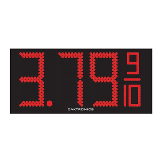
The Fuelight Series includes standard petroleum price displays. In the United States the displays employ a 9 to represent the 9/10 fraction. The displays are designed for installation in an existing or custom sign or can be mounted to a sign structure. Fuelight cabinets, specially developed for outdoor use, are constructed of heavy-gauge aluminum. -
Page 7: Mechanical Installation
The customer must also ensure the installation meets local standards. • Daktronics is not responsible for installations, the mounting structure or its structural integrity, or for the quality of the mounting hardware used to attach the displays to the support structure. Structure and attachment must conform to all applicable building codes. -
Page 8: Connecting Display Sections
1� Lift the display into the support structure. Refer to Figure 5. Note: Daktronics assumes no liability for display damage or injury resulting from incorrect setup or incorrect lifting methods. 2� Use 3/8-16 bolts and the four mounting holes in each section to attach the display to the sign cabinet. -
Page 9: Installing The Display On Horizontal Beams
Installing the Display on Horizontal Beams See DWG-1154625 for more detailed information regarding this type of installation. Use the display shop drawing to locate the holes used to attach 3/8-16 Threaded Insert the mounting hardware in this installation type. Clip Angle Two horizontal beams must be provided to accommodate the Fuelight Petroleum Price... -
Page 10: Electrical Installation
• Size conductors of circuits delivering power to a Daktronics display according to local and national electrical codes so that the power distribution systems can deliver full- load power to the display while maintaining a voltage within 5 percent of the utility nominal voltage. -
Page 11: Access Internal Components
The displays still require a safety ground from the electrical service panel for the primary power wires to comply with national electric codes. Please note that local earth ground electrode requirements for other Daktronics products remain unchanged. Power Installation Install Daktronics Fuelight displays using a two wire plus ground circuit. -
Page 12: Display Interconnections
Display Interconnections DS1 (J16) COMM LINE PORT POWER IN STATUS LINE 24 DC Line-To-Line Cable Installation DS2 (J10)* LINE TO CASH/ CREDIT LINE COMM PORT DS3 (J9)* LED Driver DS4 HEARTBEAT 1 SEC. BLINK = OK DIGIT 4 In the display, the driver, shown in Figure 10, POWER switches digits on and off. - Page 13 3� Place the 6-32 nut on the stud and tighten it with a " nut driver. Refer to Figure 13. 4� Route the provided line-to-line cable from the host driver jack J9 to the next client display driver, connecting to jack J10. Refer to Figure 14. 5�...
-
Page 14: Cash/Credit Display Installation
Cash/Credit Display Installation Cash/Credit displays are drop-in displays designed for installation with Fuelight price displays. Green or red LEDs are used in Cash/Credit displays to illuminate text. An FLR3-100/400 key fob remote or a DM-100 handheld controller are used to control Cash/Credit displays. -
Page 15: Display Identification
1� Lift displays into the support structure. Figure 23 shows a display being inserted into a support structure. Note: Daktronics assumes no liability for display damage or injury resulting from incorrect setup or incorrect lifting methods. 2� Drill through the front flanges of the cabinet to attach the display to the base structure using appropriate hardware for site conditions. -
Page 16: Grounding
Like Fuelight displays, Cash/Credit displays do not require a local earth ground electrode� Power Installation Install Daktronics Cash/Credit displays using a two-wire plus ground circuit. The ground from the circuit must be connected to the grounding stud within each Cash/Credit display. -
Page 17: Control Options Setup
Control Options Setup Refer to the quick guides provided with display communications for more information on signal installation. Quick Guide Document Number LINE DD2291475 FLR3-100 Installation Quick Guide DD2239290 FLR3-400 Installation Quick Guide DD2552313 FLR3-1500 Installation Quick Guide DD2291480 FLD3-2000 Installation Quick Guide LL-2855 REV00 Find communication installation videos at www.youtube.com/... -
Page 18: Setting The Security Dip Switches
9� Connect the receiver cable from receiver to the driver. Refer to Figure 31. Receiver Driver Antenna Cable Digit Cabinet Figure 31: Final Receiver Assembly 10� Neatly secure any excess cable with cable ties. 11� Close and secure the digit face. Setting the Security DIP Switches The FLR3-100 key fob has a series of dip switches on the back to give it a unique address setting. -
Page 19: Entering Test Mode
Entering test mode causes the displays to cycle through various pieces of information that can be useful when working with Daktronics Technical Support. 1� Press and hold the Plus -4 and +4 buttons on the key fob until the displays begin cycling through test mode. -
Page 20: Server Radio Installation
• Client radio within 25 feet of display • For best results, mount radios at equal elevation • Mount radios away from range-reducing • Leave 360-degrees of open space elements (walls, vegetations, etc.) and metal around antenna objects 2� Set the same channel inside both radios. Server Radio Installation Handheld 1�... -
Page 21: Client Radio Installation
Client Radio Installation Client Radio 1� Turn off power to the display Inside during the installation of the Display radio. Cabinet 2� Mount the client radio at or POWER within 25 feet (8 meters) of the 24 DC display. Cable DIGIT 4 3�... -
Page 22: Fld3-2000 Connection
FLD3-2000 Connection Connects directly to a J-box at the base of the display or at an indoor location and has a Is Not maximum range of 2,000 feet. Used The console’s liquid crystal display (LCD) guides the user through the operation of the system. Refer to the control quick guide that came in the control kit, for information on connection Is Not... -
Page 23: Outdoor J-Box Installation
Outdoor J-box Installation 1� Choose a location on the support pole so the J-box is easily accessible for plugging in the handheld controller. 2� Orient the box so the quick-connect cable runs out the bottom of the box. 3� Permanently fasten the J-box vertically once it has been proven effective in the location. -
Page 24: Flxr3 Server Radio Kit
FLXR3 Server Radio Kit FLXR3 Server Radio components are shown in Figure 40. The letter for each component is noted in steps that follow. Letter Component Type Letter Component Type Pole-Mount Hardware Antenna Adapter Wall Pack Transformer High Gain Antenna Antenna Extension Cable - 50' Server to DM-100 Interconnect Cable - 10' DIN Rail Mount/Track... -
Page 25: Antenna
Figure 47, that is elevated further off the ground, has improved line of sight to the server radio antenna, and within 10 feet of the client radio. Daktronics provides a 10-foot antenna extension cable to allow Figure 46: New Radio Enclosure for optimal antenna placement. -
Page 26: Flxr3 Client Radio Set Up
FLXR3 Client Radio Set Up By default, each client defaults to SU#1 and Network #1. Configure each client radio in sequence by completing the following steps: 1� Change the client radio number by pressing the reset button, shown in Figure 48, for 5 seconds to enter configuration mode. -
Page 27: Server Radio Set Up
Radio ID Client Radio Number IP Address Following successful boot up, the client radios show signal strength. Note: Signal strength will not show until the server radio is setup with client ID and sequence. Server Radio Set Up Configure the server radio through a web interface by attaching an Ethernet cable from the radio to a Figure 54: Bars Show Signal computer and completing the following steps. -
Page 28: Quality Of Service
3� Enter radio ID numbers. 4� Enter the Network Number. 5� Set TX Power to 27dBm. Capture this Warning: Applying Power to information after more the radio without an attached than 10 antenna may cause damage! manual price updates 6� Click Apply. Note: If communication issues arise, record the Radio RSSI, Radio Total... -
Page 29: Rssi Values
Quality of Service number may take a few minutes to reach 100 percent. Handheld Controller Insert and Code The handheld controller uses a keypad insert to program UPDATE DISPLAY price information for Daktronics LED Fuelight Displays. The controller’s insert is used to control the displays. Refer to Figure 59. -
Page 30: Using The Flr3-100/400 Key Fob
Using the FLR3-100/400 Key Fob Setting the Display Line Numbers Follow these steps to map the line number for each display. It is important that each display is set for the correct line number for it to show the correct price. 1�... -
Page 31: Edit Prices On The Display
Aut is shown on the display when in Automatic Dimming Mode. c� Use the -2 and +2 buttons when in Manual Dimming Mode to adjust the brightness level. Contact the Daktronics help desk at 800-325-8766 for assistance modifying manual brightness levels. -
Page 32: Select Active Price States
Price State Number State 1 State 2 State 3 1, 2 1, 3 2, 3 1, 2, 3 Standard content shown. Custom content is available and will vary from what appears above. When in configuration mode, numbers that represent selected active price states are shown on the Fuelight display. -
Page 33: Edit Cash/Credit Display Hold Time
4� Wait about 10 seconds again until the Cash/Credit display shows Debit, the third active price state. Use the minus and plus buttons on the line you are editing to revise the debit price. 5� Repeat the steps above for each line. 6�... -
Page 34: Fuelight Systems
6� Shut down power after 5 minutes� 7� Repeat this step for additional Fuelight systems. 8� Once all key fobs are synced and marked to designate which Fuelight system they control, power up all branch circuits. 9� Key fob synchronization is complete. 10�... -
Page 35: Using The Flr3-1500 And Fld3-2000
Using the FLR3-1500 and FLD3-2000 Controller After power and signal installation, set up the controller using the following steps. Set Gas Price Function Connect the DM-100 Handheld Controller To operate petroleum price displays, the handheld controller must first be programmed to the gas price function. -
Page 36: Network And Display Discovery
LED Screen Action DISPLAY $000�0 Press the Enter key to accept decimal point location change. • ENTER TO UPDATE Network and Display Discovery The controller automatically begins detecting networks. Each client radio is referred to as a network. LCD Screen •... -
Page 37: Display Menu
Display Menu LCD Screen Action PRICE OPTIONS ENT TO SELECT Press the Up and Down Arrow keys to select the Active Price States • ACTIVE PRICES (Cash, Credit, Debit), that you want to show on the display. See ↓↑ the next section for more formation on Active Price States. Press ENTER. -
Page 38: Set Active Price State Prices
When in configuration mode, numbers that represent selected active price states are shown on the DM-100 screen. Set Active Price State Prices LCD Screen Action Press ENTER to change prices for Price 1 - Cash. • LINE 1 PRICE 1 Press the CLEAR/SET FUNCTION button. -
Page 39: Active Prices
3� Press the Down Arrow key to GENERIC, press ENTER. Line 1 Product: enter 1, press ENTER (Gas Price). • Line 2 Product: enter 2, press ENTER (Diesel Price). • Line 3 Product: None, press ENTER. • Line 4 Product: None, press ENTER. •... -
Page 40: Configuration - Style
• Once the PoS or Cell Modem has reconnected, the prices from the PoS or Fuelink software will the manually entered prices. • Offsets are used in conjunction with a PoS or Cell Tails and 9/10 modem connection because only one price for each fuel grade is sent from a PoS or Fuelink software. -
Page 41: Diagnostics Menu
(p�40) for instruction to change to Manual Dimming. 1� Press the Up or Down Arrow buttons to select Configuration. 2� Press ENTER. 3� Press the Down Arrow button to select Dimming. 4� Press ENTER. LCD Screen Action Press ENTER. MAX DIMMING: 03F ENT TO CONFIRM Press ENTER. -
Page 42: Detect Displays
Detect Displays LCD Screen Action Press ENTER to detect networks and displays. • DETECT DISPLAYS ENT TO BEGIN • The DM-100 moves to the next Diagnostic option automatically. Test Patterns LCD Screen Action Press ENTER. • TEST PATTERNS Press the Up and Down Arrow keys to move to another test pattern •... -
Page 43: Com Port Tests
Com Port Tests LCD Screen Action Press ENTER. • COM PORT TESTS ENT TO SELECT Press ENTER to run test. • • Watch the screen on the DM-100 for test results SELECT TEST ↓ RS232 COM0 Press the CLEAR/SET FUNCTION button to go back. •... -
Page 44: Dimming
Dimming Adjust the dimming either Automatically or Manually. 1� Press DIMMING on the keypad. The current setting is shown on the bottom line of the LCD. Note: Displays ship from the factory in Automatic Dimming Mode. a� Automatic Dimming uses a light sensor located in each display’s decimal to detect the level of ambient light at the display location and dims the sign’s LEDs accordingly. -
Page 45: Maintenance And Troubleshooting
Maintenance and Troubleshooting Important Notes: • Visit Daktronics Support videos at www.youtube.com/daktronicssupport. • Disconnect power before any repair or maintenance work is done on the display. • Qualified service personnel must make any access to internal display electronics. • Disconnect power when the display is not in use. Leaving power on for prolonged periods of time shortens the life of some electronic components. -
Page 46: Multi-Pylon Troubleshooting Steps
Symptom/Condition Possible Cause Possible Solution Set a different line number for each display on each face refer to Setting Multiple-line sign with all the Display Line Numbers (p�26) and lines showing the same Display line addressing not Configuration - Line Mapping (p.34) prices, or data appears on set correctly. - Page 47 7� Power up the DM-100 handheld controller. Note: Do not press any buttons on the DM-100 while displays and controller are booting up� 8� Allow time for DM-100 to boot up and initialize all pylons. a� About 1 minute for each wirelessly connected pylon b�...
-
Page 48: 10 Replacement Parts
Figure 69 with the part number in bold. Use the part number on the label to easily identify replacement parts. Replacement Part Numbers Refer to Section 11: Daktronics Exchange and Repair & Return Programs (p�46) for instructions on obtaining parts from Daktronics. Part Description... - Page 49 Part Description Part Number Part Description Part Number Green Decimal (for both 36" 48" Red Horizontal Segment 0A-1735-5123 0A-1611-5332 and 48") 36" White Horizontal Segment 48" Red Vertical Segment 0A-1735-5124 0A-1735-5921 (FL-3000 Series Only) 18" Red Digit (to represent 9 of 36"...
-
Page 50: Daktronics Exchange And Repair
In most circumstances, the replacement part will be invoiced at the time it is shipped. If the failed part or replacement part is not returned to Daktronics within 3 weeks of the ship date, it is assumed that the customer is purchasing the replacement part and will be invoiced for the value of the new sale part. - Page 51 Repair & Return Program For items not subject to exchange, Daktronics offers a Repair & Return Program. To send a part for repair, follow these steps: 1� Call or fax Daktronics Customer Service: Phone: 888-DAK-SIGN (888-325-7446) Fax: 605-697-4000 2� Receive a Return Materials Authorization (RMA) number before shipping.
- Page 52 This page intentionally left blank.
- Page 53 To obtain copies of shop drawings or other reference drawings specific to your display, click the link below, enter the drawing number in the search box at the top-right side of www.daktronics.com, or contact Daktronics Customer Service at 888-DAK-SIGN (888-352- 7446).
- Page 54 This page intentionally left blank.
- Page 55 Daktronics Warranty and Limitation of Liability Click here to view Warranty and Limitation of Liability (SL-02374) information. Daktronics Warranty and Limitation of Liability...
Need help?
Do you have a question about the FUELIGHT FL-3000 Series and is the answer not in the manual?
Questions and answers