Table of Contents
Advertisement
Quick Links
Advertisement
Table of Contents

Subscribe to Our Youtube Channel
Summary of Contents for IWAKI PUMPS MDG-H2
- Page 1 MDG-H2 (built-in type) Read this manual before use of product...
-
Page 2: Table Of Contents
Contents Item Page Safety Instruction ..........1 Introduction ............2 Construction ............3 Points of Care in Handling ........4 Installation, Piping and Wiring ......5 Operation and Maintenance ........6 Troubleshooting ............. 7 Replacement ............8 Spare Parts ............9 EC DECLARATION OF CONFORMITY ...11 Information on CE conformity ......12... -
Page 3: Safety Instruction
Safety Instruction Warning Caution Turn off the power supply. Qualified operators only! Working without disconnecting the power supply may The pump operator and pump operation supervisor must cause an electrical shock. Before engaging upon any not allow any operators who have little or no knowledge working procedures involving the pump, make sure to turn of the pump to run or operate the pump. -
Page 4: Introduction
Introduction This MDG pump is made of the finest quality materials and, with reasonable care and mainte- nance, will provide excellent service. The information in this manual will help you to obtain the most satisfactory service from the MDG pump. We suggest you read it carefully before pro- ceeding with the installation and operation. -
Page 5: Construction
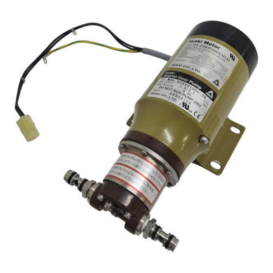
Construction When the drive magnet connected with the motor shaft is rotated, the driven magnet is rotated by magnetic force with the rear casing between, thus rotating the drive gear connected with it. The driven gear is rotated by engagement with the drive gear, so that liquid is transferred by engagement of the two gears rotating in the gear case. -
Page 6: Points Of Care In Handling
Points of Care in Handling 5. Do not use liquid containing ferric or nickel 1. Never run the pump dry. Otherwise, the powder, because the pump has a strong mag- pump bearing may be seized or worn out net in it. earlier than usual. -
Page 7: Installation, Piping And Wiring
Installation, Piping and Wiring When a pressure gauge is provided in the Installation pump discharge line piping, pressure setting Install the pump in places where the ambient of the relief valve can be easily done. temperature is 40°C or less and the rela- tive humidity is 90% or less. -
Page 8: Operation And Maintenance
Operation and Maintenance Setting the relief valve pressure Turn on the power with the valve on the dis- charge side fully opened and adjust the valve This pump has a relief valve in the end disk gradually. (When using the negative suction, so that discharge pressure can be changed by fill the suction hose and pump chamber with operating the valve. -
Page 9: Troubleshooting
Troubleshooting Troubles Causes Remedies Motor does not 1. Plug is disconnected from 1. Plug in receptacle. start. plug receptacle. 2. Defect of wiring, break of 2. Check and change, if necessary. wire. 3. Defect of motor, break of 3. Repair or change. wire. -
Page 10: Replacement
Replacement This pump is made with extreme precision. In case of dismantling and reassembling, carefully handle each part and also use care to prevent a damage to the seal surface. Special care should be taken when dismantling the pump, because the liquid may sometimes 2. -
Page 11: Spare Parts
Spare Parts Replacing the motor In order to run the pump continuously for a If bearing sound or other abnormal states long period of time, proper service kit are are found in the motor 1, replace the motor indispensable. It is recommended that expend- assembly with a new one. - Page 12 Description Q'ty Remarks Mot or Sc rew M4×6 G a sket Mou nt i ng plat e Valve Spr i ng Spr i ng seat Valve ga sket Cla mp nut Adju st i ng sc rew M4×16 Rea r ca si ng D r ive n mag net D r ive mag net Mou nt i ng d isk...
-
Page 13: Ec Declaration Of Conformity
EC DECLARATION OF CONFORMITY ORIGINAL VERSION (SUPPLIER’S NAME) IWAKI CO.,LTD. (ADDRESS) 6-6 2-CHOME KANDA-SUDACHO CHIYODA-KU TOKYO JAPAN (PRODUCT) DECLARE UNDER OUR SOLE RESPONSIBILITY THAT THE PRODUCTS MAGNETIC DRIVE GEAR PUMP (MODEL NAME) MDG SERIES TO WHICH THIS DECLARATION RELATES ARE IN CONFORMITY WITH THE FOLLOWING STANDARDS OR DIRECTIVES AS FAR AS APPLICABLE (DIRECTIVES) MACHINERY DIRECTIVE 2006/42/EC (ANNEX IIA) -
Page 14: Information On Ce Conformity
Information on CE conformity - Motor conformity in accordance with any relevant EC directives which are currently effective. - The motor must be installed to the pump according to this instruction manual. - Guaranteed grounding - The pump must not be repainted over our original upper coating. Any reseller or dealer who connects the pump with a motor and markets it as a complete unit must conform to all relevant EC directives. - Page 15 — —...
- Page 16 TEL: +61 2 9899 2411 FAX: +61 2 9899 2421 Germany / IWAKI Europe GmbH Sweden / IWAKI Sverige AB China (Hong Kong) / IWAKI Pumps Co., Ltd. TEL: +49 2154 9254 50 FAX: +49 2154 9254 55 TEL: +46 8 511 72900 FAX: +46 8 511 72922...


Need help?
Do you have a question about the MDG-H2 and is the answer not in the manual?
Questions and answers