
Related Manuals for IWAKI PUMPS MXM Series


Summary of Contents for IWAKI PUMPS MXM Series
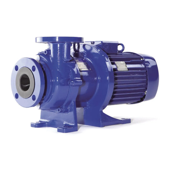
- Page 1 IWAKI Magnetic Drive Pump MXM ( Asia version: English ) Instruction Manual Read this manual before use of product...
-
Page 2: Table Of Contents
Thank you for selecting an Iwaki MXM Series Magnetic Drive Pump. This instruction manual deals with "Safety instructions", "Outline", "Installation", "Operation", and "Maintenance" sections. Please read through this manual carefully to ensure the optimum performance, safety and service of your pump. -
Page 3: Important Instructions
Important instructions For the Safe and Correct Handling of the Pump ● "Safety Instruction" section deals with important details about handling of the product. Before use, read this section carefully for the prevention of personnel injury or property damage. ● Observe the instructions accompanied with "WARNING" or "CAUTION" in this manual. These instructions are very important for protecting users from dangerous situations. -
Page 4: Safety Instructions
Safety instruction WARNING ● Access limitation The magnet drive pump has a pair of strong magnets (the magnet capsule unit and drive magnet). The strong magnet field could adversely affect the Prohibited persons who are assisted by electronic devices such as the pacemaker. ●... - Page 5 Safety instruction CAUTION ● Attention to magnetic force Strong magnets are used in this pump. Personal injury may be caused from the strong magnetic force. Follow the procedure on "Disassembly & Assembly" when conducting maintenance work. ● Do not run pump dry Running the pump without liquid, friction heat damages the inside of pump.
-
Page 6: Outline
Outline 1. Unpacking & Inspection ......5 2. Model codes ......... 6 3. Operating conditions ......7 4. Part names ........... 8 - 4 -... -
Page 7: Unpacking & Inspection
Outline 1. Unpacking & Inspection On unpacking the product, check the following points. If you find any problems, contact your nearest distributor. 1. Check the information on nameplate (model code, flow rate, discharge pressure and voltage) to see if the product is delivered as per order. 2. -
Page 8: Model Codes
Outline 2. Model codes MXM 54 3 - 150 3 E CF V J - B a. Pump bore Inlet bore × Outlet bore 22: 25A × 25A 44: 40A × 40A 54: 50A × 40A b. Motor output 0: 0.4kW 1: 0.75kW 2: 1.5kW 3: 2.2kW 5: 3.7kW c. -
Page 9: Operating Conditions
Outline 3. Operating conditions Maximum operating pressure Observe the maximum operating pressure below. MXM220/221 MXM441/442 High temperature type (H) High temperature type (H) Temp. Temp. (°C) (°C) MXM542/543/545 Ambient temperature: 0-40°C High temperature type (H) Relative humidity: 35-85%RH 0.45 NOTE: The minimum liquid temperature for ®... -
Page 10: Part Names
Outline MXM220 4. Part names 903.1 554.1 903.1 554.1 903.5 903.1 554.1 903.2 554.1 858 901.1 554.2 330.1 330 908.1 859 158 100.3 903.3 100.2 230 100.1 122.1 400.2 100.4 314.1 314.2 903.4 314.3 400.1 PART NAMES Q'TY MATERIAL REMARKS 100.1 FRONT CASING CFRETFE... - Page 11 Outline MXM220H 858 901.1 554.2 908.1 330.2 330 554.4 901.3 900 100.3 903.3 100.2 230 100.1 903.1 554.1 903.1 554.1 903.5 903.1 554.1 903.2 554.1 122.1 400.2 100.4 314.1 314.2 903.4 314.3 400.1 PART NAMES Q'TY MATERIAL REMARKS 100.1 FRONT CASING CFRETFE 100.2 COVER A...
- Page 12 Outline MXM221/ 221H 858 901.1 554.2 908.1 330 158 100.3 903.3 100.2 230 100.1 903.1 554.1 903.1 554.1 903.5 903.1 554.1 903.2 554.1 122.1 400.2 100.4 314.1 314.2 903.4 314.3 400.1 PART NAMES Q'TY MATERIAL REMARKS 100.1 FRONT CASING CFRETFE 100.2 COVER A 100.3...
- Page 13 Outline MXM441/ 441H/ 442/ 442H 903.5 903.1 554.1 903.2 554.1 903.2 554.1 801 901.1 554.2 858 330 908.1 900 859 100.3 903.3 158 100.2 230 100.1 122.1 400.2 100.4 314.1 314.2 903.4 314.3 400.1 903.2 554.1 PART NAMES Q'TY MATERIAL REMARKS 100.1 FRONT CASING...
- Page 14 Outline MXM542/ 543/ 545 903.5 903.1 554.1 903.2 554.1 908.1 901.1 554.2 100.3 903.3 100.2 100.1 122.1 400.2 100.4 314.1 314.2 903.4 314.3 400.1 PART NAMES Q'TY MATERIAL REMARKS 100.1 FRONT CASING CFRETFE 100.2 COVER A 100.3 COVER B DUCTILE IRON 100.4 COVER C 122.1...
- Page 15 Installation 1. Before installation ....... 14 2. Pipework ..........15 3. Wiring ..........17 4. Protection equipment ......18 - 13 -...
-
Page 16: Before Installation
Installation 1. Before installation 1. Discharge line 2. Gate valve 3. Check valve 4. Pressure gauge 5. Motor 6. Magnetic drive pump 7. Expansion joint Within 1m 8. Vacuum (compound) gauge 9. Straight suction line 10. Suction line 11. Air vent line 12. -
Page 17: Pipework
Installation 2. Pipework ■ Tightening torque between the pump and pipework Connect the pump to pipework via inlet and outlet flanges according to the tightening torque below. Tighten bolts diagonally at even tension. Model Bolt size Tightening torque MXM22/44/54 79N•m NOTE1: The table is based on use of metal pipe flanges with rubber gaskets. - Page 18 Installation ■ Suction line 1. Flooded suction application Always realize the flooded suction. 2. Suction line bore A suction line bore should be equal to or larger than pump inlet. 3. Shortest line length Keep the shortest length with the minimum number of bends. 4.
-
Page 19: Wiring
Installation ■ Discharge line 1. Discharge line bore When a discharge line is long but its bore is equal to the pump outlet bore, the specified performance may not be obtained because pipe resistance becomes high. Calculate pipe resistance in advance to decide a discharge line bore. -
Page 20: Protection Equipment
Installation 4. Protection equipment It is recommended to install the following monitoring devices in order to protect the pump. 1. Current sensor/ Power sensor The sensors monitor the motor load and stop the pump on the detection of load change, giving an alarm. 2. - Page 21 OPERATION 1. Before operation ......... 20 2. Operation ..........21 3. Shutdown ..........22 - 19 -...
-
Page 22: Before Operation
Operation 1. Before operation CAUTION ● Never run pump dry or shut off a suction valve during operation. Otherwise, the pump fails in a short period. Especially for the FF types, the bearing and spindle can be damaged in a quite-short time of about one minute. Prohibit ●... -
Page 23: Operation
Operation 2. Operation 1. Fully close a discharge valve and fully open a suction valve. 2. Prime the pump. • If the pump is in the flooded suction application, fully open both discharge and suction valves. • If the pump is in the suction lift application, prime a suction line as well as the pump. 3. -
Page 24: Shutdown
Operation 3. Shutdown 1. Slowly close a discharge valve. Quick closing by a solenoid valve may cause water hammer and damage the pump. Be sure to slowly close any discharge valve. 2. Switch off and stop the pump. Check that the pump stops smoothly. If the pump stops roughly, make an inspection. NOTE: When leave the pump stopped for a long period... - Page 25 Maintenance 1. Troubleshooting ........24 2. Maintenance & Inspection....26 3. Disassembly & Assembly....29 4. Spare & Wear parts ......36 - 23 -...
-
Page 26: Maintenance 1. Troubleshooting
Maintenance 1. Troubleshooting Turn off power to stop operation upon sensing abnormalities. And then look for a root cause or contact us as necessary. Symptom Point to be checked Troubles Cause & When a discharge When a discharge Countermeasures valve is closed. valve is opened. - Page 27 Maintenance Symptom Point to be checked Troubles Cause & When a discharge When a discharge Countermeasures valve is closed. valve is opened. The motor is • Voltage has dropped • Check voltage or fre- overheated. greatly. quency. • Overload • Check specific gravity and viscosity of liquid.
-
Page 28: Maintenance & Inspection
Maintenance 2. Maintenance & Inspection WARNING ● Access limitation The magnet drive pump has a pair of strong magnets. The strong magnet field could adversely affect the persons who are assisted by electronic devices such as the pace- maker. ● Do not catch the finger The magnetic force of the pump is powerful. - Page 29 Maintenance ■ Periodic inspection To ensure efficient and smooth operation, perform periodic inspection. Be careful not to damage internal sliding parts and plastic parts when dismantling the pump. The magnetic force of the drive magnet unit and magnet capsule assembly is strong. Be careful not to catch the finger.
- Page 30 Maintenance ■ Wear limits of bearing and spindle * If the clearance between the inner diameter of the bearing and the outer diameter of the spindle exceeds 1 mm, either the bearing or spindle, whichever has greater wear, should be replaced regardless of the wear limit.
-
Page 31: Disassembly & Assembly
Maintenance 3. Disassembly & Assembly WARNING ● Access limitation The magnet drive pump has a pair of strong magnets. The strong magnet field could adversely affect the persons who are assisted by electronic devices such as the pace- maker. ● Do not catch the finger The magnetic force of the pump is powerful. - Page 32 Maintenance ■ Dismantlement 1. Flush out chemical liquid from the pump by Front casing a flushing line. Then remove the drain cap to empty the pump. WARNING Wear protective clothing such as goggles, rubber gloves, etc. during maintenance. Coming in contact with a harmful chemi- cal liquid may cause eye or skin trouble.
- Page 33 Maintenance Impeller 3. Pull out the impeller unit + the magnet capsule assembly. Be careful not to scratch each part. Note that the magnetic force of the magnet cap- sule assembly is strong. Keep it free from metal pieces or powder. Do not scratch any sliding or sealing surfaces.
- Page 34 Maintenance 5. Detach the impeller unit from the magnet cap- sule assembly as necessary. Be careful not to damage the units. a. MXM220/ 221/ 441/ 442 Slightly tap the back of impeller unit by plastics hammer while holding the magnet capsule assembly.
- Page 35 Maintenance After the lock pins are removed, detach the impeller unit from the magnet capsule assem- bly by slightly tapping the back of the impeller unit with a plastic hammer. If the impeller unit is hardly removed, warm it in hot water (approx.
- Page 36 Maintenance b. MXM542/ 543/ 545 U-shape hole ø3mm hole Attach the impeller unit to the magnet capsule assembly. The mating surface on the assembly has two holes. The large hole (Stepped holes with 6mm at outer dia. & 12mm at inner dia) is for the lock pins and the small hole (3mm dia.) is for cooling.
- Page 37 Maintenance 2. Insert the magnet capsule assembly plus the impeller unit into the rear casing slowly. Do not allow iron pieces to adhere to the magnet capsule assembly. Spacer 3. Mount the rear casing to the bracket with the magnet capsule assembly in it. Bracket CAUTION Magnet force is very powerful.
-
Page 38: Spare & Wear Parts
Maintenance 4. Spare & Wear parts Appropriate spare parts are necessary for a long period of continuous operation. We recommend that wear parts be always in stock. Place an order for spares with the following information. 1. Part names and part number (See the diagram below.) 2. - Page 39 Maintenance MXM22 400.1 554.2 901.1 314.3 220H only 330.2 314.2 903.3 220 only Disabled single 903.3 330.1 100.2+100.3 With 903.3×3 908.1 901.2 903.3 903.4 554.3 554.1 122.1 400.2 903.1 122.1 100.1 908.1 400.2 903.4 554.4 901.3 554.1 903.2 100.4 Disabled single (890) with 903.4×2 903.5...
- Page 40 Maintenance MXM54 400.1 314.3 314.2 Disabled single 901.1 KK type with hole 100.2+100.3 903.3 554.2 With 903.3×3 908.1 903.3 903.3 903.4 400.2 122.1 908.1 100.1 901.2 554.3 (890) 554.1 903.4 122.1 903.2 400.2 903.5 903.1 554.1 100.4 Disabled single with 903.4×2 - 38 -...
- Page 41 Maintenance - 39 -...
- Page 42 - 40 -...
- Page 43 - 41 -...
- Page 44 IWAKI Norge AS TEL : (47)66 81 16 60 FAX : 66 81 16 61 China IWAKI Pumps (Guandong) Co., Ltd. TEL : (86)750 3866228 FAX : 750 3866278 Singapore IWAKI Singapore Pte. Ltd. TEL : (65)6316 2028 FAX : 6316 3221 China GFTZ IWAKI Engineering &...
Need help?
Do you have a question about the MXM Series and is the answer not in the manual?
Questions and answers