
Subscribe to Our Youtube Channel
Related Manuals for IWAKI PUMPS MD-55F


Summary of Contents for IWAKI PUMPS MD-55F
- Page 1 IWAKI Magnetic Drive Pump MD-55F/-100F type Instruction Manual Read this manual before use of product...
-
Page 2: Table Of Contents
Important Instruction Thank you for selecting an Iwaki MD-55F/-100F type Magnetic Drive Pump. This instruction manual deals with "Safety Instructions", For the Safe and "Outline", "Installation", "Operation" and "Maintenance" sections. Correct Handling of the Pump Please read through this instruction manual to ensure the opti- ●... -
Page 3: Safety Instructions
Safety Instructions WARNING CAUTION ● Turn off power. ● Restriction on operator Risk of electrical shock. Dismantling/assem- The pump should be handled by a qualified bling the pump unit without turning off power person with a full understanding. may cause an electrical shock. Before ●... - Page 4 Safety Instructions CAUTION CAUTION ● Do not place the pump close to water. ● Power cable is not replaceable. Do not use any damaged power cable for The pump is not dust-/water-proof construc- the prevention of a fire or electrical shock. tion.
-
Page 5: Outline
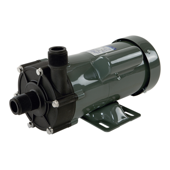
Outline 2. Operating principle Before use, check the specification, limitation and hazardous nature of the pump. The MD-F is a compact magnetic drive centrifugal pump with 1. Unpacking & Inspection fluoroplastic and fine ceramic wet ends and is capable of handling a strong acid and alkali. -
Page 6: Identification Code
No code : Standard tions. Frozen liquid can not be transferred. Gold coating f. All the single-phase motors used for the MD-55F/-100F series are f. Special version capacitor-run induction motor. No code : Standard g. -
Page 7: Outer Dimensions
Outline 5. Outer dimensions 6. Performance curves MD-55F MD-55F/-100F (58.3) (39.5) 50Hz (152) MD-100F Capacity (l/min) (63) (43) NOTE: This performance curve is collected when pumping clear water at ambient temperature under a flooded suction system. (178) - 5 -... -
Page 8: Overview & Label
Outline 7. Overview & Label Pump unit (Liquid feeding unit) Not capable of self-priming. Always prime the pump before operation. Specification label Use the pump accord- ing to the specifica- Outlet tions on the label. Motor (drive unit) Do not wet the pump and motor units. -
Page 9: Part Names & Structure
Outline 8. Part names & Structure MD-100F MD-55F 21 14 8 17 21 14 12 2 9 13 11 20 19 3 17 101 20 12 19 3 Materials Materials Part names Q'ty Part names Q'ty MD-55F MD-100F MD-55F MD-100F... -
Page 10: Installation
Installation 1. Before Installation ● Dropping or subjecting the pump to strong impact, failure may result. Read through this instruction manual before use. Carry out instal- Handle the pump with care. lation work with a full understanding. WARNING ● Risk of electrical shock. Dismantling/assembling the pump unit without turning off power may cause an electrical shock. - Page 11 Installation ● Banned solutions CAUTION • Halogenated hydrocarbons such as Do not install or store the pump in the trichloroethylene and carbon tetra- following places: chloride 1. Where ambient temperature • Ether and low-grade ester exceeds 40°C or falls below 0°C. •...
-
Page 12: Installation/Piping/Electrical Wiring
Installation 2. Installation/ Piping/ Electrical wiring 3. Outlet direction Direct the outlet upward Always direct the outlet upward or Stop working upon sensing danger or abnormality. entrained air can not be expelled. 2.1 Installation 1. Installation location Select a convenient place for maintenance and inspection. Observe the allowable room temperature range of 0-40°C and the allowable maximum ambient humidity of 90%RH. - Page 13 Installation 2.2 Piping 1. Flow/head adjustment & maintenance valves Install a ball valve on a discharge line for flow rate adjustment and ■ Before tubing on a suction line for the convenience of maintenance, as close to • Using a high flow pump and a small supply tank, a liquid level in the pump as possible.
- Page 14 Installation ■ Suction line • In order to minimize plumbing resistance, have plumbing shortest • Avoid any loops in a plumbing run that could form a vapour trap. A with the minimum bends. Note cavitation*¹ tends to occur when suction line should be laid on a rising gradient of 1/100 toward the plumbing length is too long.
- Page 15 Installation <Thread connection> • Be sure to remove a cushion from the outlet before pipework. Be careful not • Use of a Teflon pipe or a Teflon-lined to damage the wet ends. pipe is recommended. • Select a suitable pipe bore for secure connection.
- Page 16 Installation 2.3 Electrical wiring Electrical wiring must be done by a qualified person who has a full knowledge of safety. We are not responsible for the injury or damage accident due to nonobservance of this warning. Contact us or your nearest distributor for wiring as necessary.
-
Page 17: Operation
Operation 1. Before operation ■ Preparations for operation 1. Check that the pump is under a flooded suction system and a liquid Read through this section before use. in a supply tank is at an appropriate level. CAUTION 2. Check the connection between the pump and piping. 3. - Page 18 Operation ■ Operating procedure Procedure Points to be checked After installation, piping and wiring work are completed, operate the Adjust discharge • Open a discharge-side valve grad- pump in accordance with the following procedures. capacity & dis- ually till a flow and a head reach charge head to a specified level.
- Page 19 Operation ■ Degassing ■ Shutdown Open a discharge line. The end of the line immersed in liquid is not Procedure Description ideal for degassing. Take it out from liquid as necessary. Then run the Close a discharge- Close a discharge-side valve gradu- pump for one second.
-
Page 20: Maintenance
Measure then do not deform the plastic pump head. Wrong wiring Inspect wiring. Rewire as necessary. Tightening torque Motor failure Contact us. MD-55F 3.0N•m Air is trapped. Eliminate air. MD-100F 3.5N•m Air suction from the inlet Check suction piping. Dry running Prime the pump before ■... - Page 21 Maintenance 2.2 Inspection ■ Wear parts To run the pump for a long period, wear parts such as an impeller and ■ Daily inspection an O ring need to be replaced periodically. Always check for abnormality in vibration, noise, current value, and Contact your distributor for detail.
-
Page 22: Drainage
Maintenance 3. Drainage ■ Procedure No drain port is provided to this pump. See drainage procedure 1. Turn off power. Make sure no one Discharge below. turns on power while working on the valve pump. WARNING 2. Close a discharge and a suction valve Suction valve ●... - Page 23 - 21 -...
- Page 24 IWAKI Norge AS TEL : (47)23 38 49 00 FAX : 23 38 49 01 China IWAKI Pumps (Guangdong) Co., Ltd. TEL : (86)750 3866228 FAX : 750 3866278 Singapore IWAKI Singapore Pte. Ltd. TEL : (65)6316 2028 FAX : 6316 3221 China GFTZ IWAKI Engineering &...
Need help?
Do you have a question about the MD-55F and is the answer not in the manual?
Questions and answers