Advertisement
Technical Support and E-Warranty Certificate www.vevor.com/support
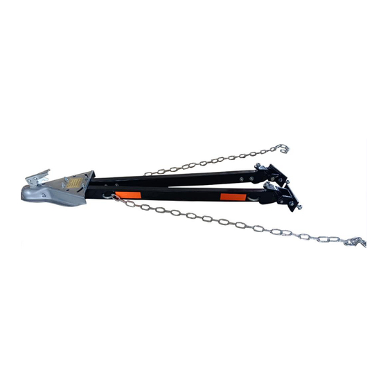
TOW BAR
MODEL: FF-T809
We continue to be committed to provide you tools with competitive price.
"Save Half", "Half Price" or any other similar expressions used by us only represents an
estimate of savings you might benefit from buying certain tools with us compared to the major
top brands and does not necessarily mean to cover all categories of tools offered by us. You
are kindly reminded to verify carefully when you are placing an order with us if you are
actually saving half in comparison with the top major brands.
Advertisement
Table of Contents

Related Manuals for VEVOR FF-T809


Summary of Contents for VEVOR FF-T809
- Page 1 Technical Support and E-Warranty Certificate www.vevor.com/support TOW BAR MODEL: FF-T809 We continue to be committed to provide you tools with competitive price. "Save Half", "Half Price" or any other similar expressions used by us only represents an estimate of savings you might benefit from buying certain tools with us compared to the major top brands and does not necessarily mean to cover all categories of tools offered by us.
- Page 3 This is the original instruction, please read all manual instructions carefully before operating. VEVOR reserves a clear interpretation of our user manual. The appearance of the product shall be subject to the product you received. Please forgive us that we won't inform you again if there are any technology or software updates on our product.
-
Page 4: Safety Instructions
SAFETY INSTRUCTIONS Failure To Follow These Instructions May Result In A Hazardous Towing Condition. 1. Total weight of the towed vehicle must not exceed 5500 lbs. 2. Towing vehicle must weigh more than towed vehicle. 3. Install per the instructions provided. 4. -
Page 5: Usage Notes
USAGE NOTES 1. Never exceed the lowest rating of any part of your towing system. 2. Use this tow bar to tow only vehicles in good condition. Do not tow vehicles with damaged steering or surension systems. 3. Inflate the tires of the towed vehicle to the maximum pressure recommended by the tire manufacturer. - Page 6 MODEL AND PARAMETERS Model FF-T809 Max. Towing Capacity 5500lbs Opening And Closing Width 39.4'' Max Coupler STRUCTURE DIAGRAM AND COMPONENTS Name Coupler(2 Tow Bar Reflective Sticker Safety Chain(1.2m) Bolt (φ12*80mm) Bolt (φ12*45mm) U-bolt U-shaped Connector Mounting Bracket User Manual - 4 -...
-
Page 7: Installation Notes
INSTALLATION NOTES 1. This tow bar will be installed by a professional installer/fabricator experienced in selecting vehicle attachment areas with adequate strength. 2. Park vehicles on level ground for installation. 3. The coupler must be level within 5°when the attachment is complete, as shown. - Page 8 TOWED VEHICLE ATTACHMENT A structure must be fabricated to allow the tow bar to be attached to the frame of the towed vehicle. Some typical frame attachment structures are shown below. If the bumper is used for support, it must be reinforced with frame attachments. A typical way of reinforcing a bumper is shown below.
- Page 9 COUPLER COUPLER ADJUSTMENT: 1. With the coupler locked onto a 2" dia. ball, tighten the locknut until all parts are clamped solid. NOTE: DO NOT OVERTIGHTEN. JUST TIGHTEN ENOUGH TO FULLY COMPRESS HELICAL SPRING. 2. Back locknut off 1/2 to 3/4 turn. 3.
-
Page 10: Installation
INSTALLATION 1. Center the tow bar on the attachment surface, spreading side arms to at least 24", and mark the tow bar bracket centerlines. 2. Using the tow bar bracket as a template, drill two 1/2" holes into the attachment surface on each side. 3. -
Page 11: Maintenance
USE SAFETY CHAIN : 1. Connect safety chains to both vehicles and the tow bar itself. 2. Attach chains to the tow bar with U-bolts and flanged locknuts. 3. Tighten each flanged locknut until U-bolt threads extend past locknut. 4. Cross two chains under the coupler and connect to the chair bracket on the hitch or to the frame of towing vehicle allowing only enough slack to permit turning. - Page 12 Technical Support and E-Warranty Certificate www.vevor.com/support...
Need help?
Do you have a question about the FF-T809 and is the answer not in the manual?
Questions and answers
how far in are the adapter holes from the end of the tow bar
The distance of the adapter holes from the end of the VEVOR FF-T809 tow bar is not provided in the available information.
This answer is automatically generated