Table of Contents
Advertisement
Quick Links
Advertisement
Table of Contents

Subscribe to Our Youtube Channel
Related Manuals for Gree ME60-42/H1


Summary of Contents for Gree ME60-42/H1
- Page 1 Owner's Manual Original Instructions Dry Contact Controller ME60-42/H1...
- Page 2 To Users Thank you for selecting Gree product. Please read this instruction manual carefully before installing and using the product, so as to master and correctly use the product. In order to guide you to correctly install and use our product and achieve...
-
Page 3: Table Of Contents
Contents 1 Safety Notices (Please be sure to abide) ......1 2 Appearance ................2 3 DIP Switch Instruction ............3 4 Functions................4 4.1 Shield General Terminals ............4 4.2 Input Function ................. 4 4.3 Output Function ..............6 4.4 Indicator Instruction .............. -
Page 4: Safety Notices (Please Be Sure To Abide)
Dry contact controller ME60-42/H1 1 Safety Notices (Please be sure to abide) WARNING: If not abide them strictly, it may cause severe damage to the unit or the people. NOTE: If not abide them strictly, it may cause slight or medium damage to the unit or the people. -
Page 5: Appearance
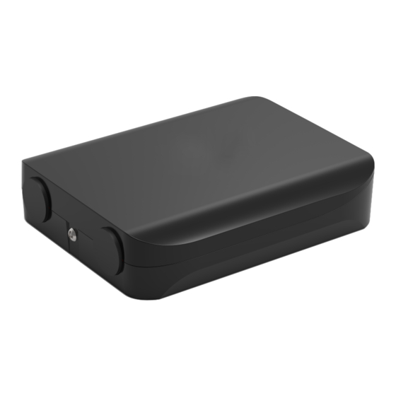
Dry contact controller ME60-42/H1 2 Appearance Figure 2-1 Appearance of dry contact controller Figure 2-2 Main board of dry contact controller... -
Page 6: Dip Switch Instruction
Dry contact controller ME60-42/H1 Table 2-1 Instruction of main board Components Components 4-core needle stand (common use for DIP switch S1 communication and power supply) Emergency off signal input ON/OFF status output ON/OFF signal input Unit faulty output Cooling/heating signal input... -
Page 7: Functions
Dry contact controller ME60-42/H1 Table 3-2 Function for DIP switch S2 Dip switch bit Cooling/ Input name Emergency OFF ON/OFF Reserved heating ON position Enable Enable Enable Digital position Disable Disable Disable 4 Functions 4.1 Shield General Terminals Once the first bit of DIP switch S1 is set to Digital position (General terminals... - Page 8 Dry contact controller ME60-42/H1 4.2.1 Level Input Under level input method, the input command is decided by the Connected/Disconnected of the dry contact. Each time when the status of dry contact is changed, input commands of all the dry contacts will be re-executed. The relationship between dry contact status and the input command are shown as the table 4.1.
-
Page 9: Output Function
Dry contact controller ME60-42/H1 Table 4-2 Impulse input Input name Machine state Machine type Command With Emergency off Cancel Emergency off Emergency off Without Emergency off Emergency off (default when energized) Machine on Turn off the unit ON/OFF Machine off... -
Page 10: Indicator Instruction
Dry contact controller ME60-42/H1 Table 4-3 Function definition of output contact Output dry contact Contact connected Contact disconnected ON/Off status Unit on Unit off Unit faulty Unit Faulty Normal Operating mode Heating Cool/Dry/Fan Cold plasma Turn cold plasma on Turn cold plasma off... -
Page 11: Product Installation
Dry contact controller ME60-42/H1 5 Product Installation 5.1 Dimension Figure 5-1 Dimension of dry contact controller (unit:mm) 5.2 Installation Requirement (1) Do not install the product at wet place or the place where there’s splashing water. (2) Do not install the product at the place where is closing to the high-temperature object or the position with direct sunshine. -
Page 12: Wire Specification
Dry contact controller ME60-42/H1 operation is below 2000 meters. (4) Before installation, please cut off the power for the strong wire embedded in the installation hole on the wall. Ho-line work is not allowed during the complete installation process. (5) Please pay attention to below notices for wiring to avoid abnormal phenomenon due to electromagnetic interference. -
Page 13: Wiring Instruction
Dry contact controller ME60-42/H1 5.4 Wiring Instruction 5.4.1 Communication and power cord connection Connect one end of wiring (4-core wire) to the COM1 needle stand of dry contact controller and then connect the other end to the 4-core COM3 needle stand of the indoor unit (The port number of the indoor unit is subject to the actual matching indoor unit). - Page 14 Dry contact controller ME60-42/H1 Figure 5.2 Sketp map for input/output wiring 5.4.4 Installation Procedure (1) Remove the screws used for fixing the front cover; Open the front cover of dry contact controller. (2) Check whether the screws used for fixing the main board is loose. If yes, please tighten the screws to fix the main board.
- Page 15 Dry contact controller ME60-42/H1 and the protective jacket of the wire can put through the rubber ring and wire clamp. (6) Connect the wire to corresponding terminals, and screw up the screw in the contact to make sure that it will not loose.
Need help?
Do you have a question about the ME60-42/H1 and is the answer not in the manual?
Questions and answers