Table of Contents
Advertisement
Quick Links
Advertisement
Table of Contents

Subscribe to Our Youtube Channel
Related Manuals for Point Mobile PM251


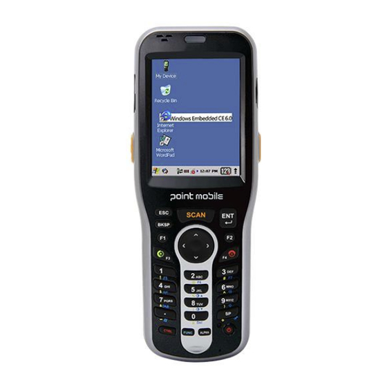
Summary of Contents for Point Mobile PM251
- Page 1 PM251 WinCE 6.0 User’s Guide...
-
Page 2: Table Of Contents
Suspend Mode ··································································································· 33 4.21. Memory Allocation ······························································································· 33 4.22. Care and Cleaning of the Products ·········································································· 33 4.23. PM251 Technical Specifications ············································································· 34 5. USING THE KEYPAD ··········································································· 36 5.1. Numeric Keypad Layout ······················································································· 36 5.2. Navigation Keys ·································································································· 36 5.3. - Page 3 5.6. White Indicators on the Numeric ············································································· 37 5.7. BLUE Key Combinations ······················································································ 38 5.8. Program Buttons ································································································· 39 6. USING THE IMAGE ENGINE ································································· 40 6.1. Overview ··········································································································· 40 6.2. Available Image Engines ······················································································ 41 6.3. Depth of Field ····································································································· 41 6.4.
- Page 4 Software Requirements for Communication ··················································· 60 10.8. Setting Up the Host Workstation ·································································· 60 10.9. Communicating with the PM251 ·································································· 60 10.10. Synchronizing with the Host Workstation ······················································· 61 10.11. Exploring the Terminal from the Workstation ·················································· 61 10.12. Adding Programs via ActiveSync ································································· 61 10.13.
-
Page 5: Introduction
About the PM251 The new PM251 is the latest generation PM251 device, built on Microsoft Windows Embedded CE 6.0 Pro operating system. The PM251 is designed for retail warehousing and logistics applications where maximum performance and durability is required in compact Handheld device. -
Page 6: Safety Regulations
However, as with any electrical equipment, the best way to ensure safe operation is to read this manual carefully before performing any type of connection to the PM251 and operate them according to the agency guidelines described in the manual. -
Page 7: Power Supply
Ne tentez pas de démonter le PM251. Ce produit ne contient aucune pièce ne pouvant être réparée par l'utilisateur. Toute manipulation fera perdre la garantie au produit. Lors du remplacement de la batterie ou en fin de vie du terminal portatif PM251, l'élimination et le recyclage doit être effectuée en conformité avec les lois en vigueur dans votre pays. - Page 8 The following information is provided to comply with the rules imposed by international authorities and refers to the correct use of PM251. Laser Safety Statement This product has been tested in accordance with and complies with CDRH 21 CFR 1040.10 and 1040.11 and IEC 450825-1 Ed 2 (2007) except for deviations pursuant to Laser Notice No 50, dated...
-
Page 9: Getting Started
3. Getting Started 3.1. Install the Battery PM251 is shipped with the battery packaged separate from the unit. To install the battery, release the hand strap, remove the battery door by turning the locks upward, insert the battery with the labels facing upward, and replace the battery door. - Page 10 Insert the plug into the appropriate power source. Plug the PM251 power cable into the DC Jack at the bottom of the unit. 3.2.2 Charging with I/O connector If you use the Communication Cable, slide the cable unit onto the bottom of the terminal lining up the terminal’s I/O connector with the cable unit’s connector.
-
Page 11: Led Indicators
LED is green constant. If the battery pack is removed from the PM251, it can be recharged by inserting it into the rear slot of the single slot cradle, the single Ethernet cradle or the 4-slot battery charger. -
Page 12: Turn Your Device On
If the battery is not sufficiently charged, PM251 does not turn on. In this case, either substitute the battery pack with a charged one (sufficiently charged) or insert PM251 into a powered cradle or plug it into the direct power supply. -
Page 13: Desktop
3.6. Desktop ☞ NOTE: You can access the Desktop any time by tapping the Change Views icon in the command bar and selecting Desktop on the popup menu Tab to change views 3.7. Indicator Icons The command bar, located at the upper of application screens, provides access to many system functions and programs. -
Page 14: Using The Stylus
Displays the current time. Double tap to change the time and date. Indicates whether the keypad is standard alpha (upper and lower case), all caps alpha, or in numeric mode. Press the ALPHA button on the keypad to switch modes. Icon Meaning The up arrow allows you to turn the Wireless LAN and Bluetooth connection... -
Page 15: Using Windows Explorer
4. Get to Know Your Device 4.1. Feature of Your Device The following list outlines a few of the feature included in your device. 4.2. PM251 Operating Systems: Microsoft Windows Embedded CE 6.0 Pro ➢ Micro Processor: Cortex-A8 1GHz ➢... -
Page 16: Front Panel Layout
1) Power indications, 2) Scan reading indications 3) OS notifications Notification Vibration Motor ➢ 4.3. Front Panel Layout LED Indicator Shows the information needed to operate your device as follows: Note: The LED is user-programmable. LED Color Meaning ➢ Power indications Lights when main battery is charging Blinks when the battery is very low (<10%) Lights when the battery is low (<20%) -
Page 17: Display Backlight
Keypad 28 numeric keypad (Alpha shifted) 2 Side Scan triggers Microphone The integrated microphone can be used for audio recording. Touch Screen Display The display is a LCD (Liquid Crystal Display) with a Capacity touch screen. The 2.8” QVGA is transmissive active matrix color and backlit. -
Page 18: Keypad Backlight
☞ NOTE: Using the backlight option while on battery power substantially reduces battery life. You may make the same changes when on external power by tapping the External tab. 4.5. Keypad Backlight To turn on the keypad backlight, check the checkbox. The duration of backlight of keypad synchronizes with LCD backlight’s. - Page 19 protector smoothly and remove any air bubbles. Press the Power key to put the terminal in suspend mode. Clean the touch panel thoroughly with a clean, non-abrasive, lint-free cloth, Make sure nothing is on the touch panel. Blue tag with backing film: Peel off this mask before application. Align the exposed edge of the screen protector along the left edge of the touch panel.
- Page 20 Press the Power key to weak the terminal and check the touch panel with the stylus. Verify that the screen accepts input from the stylus as usual. If not, re-apply the screen protector. Press the Power key to put the terminal back in suspend mode. 10.
-
Page 21: Back Panel Layout
13. Tap Recalibrate the follow the instructions on the screen. 4.8. Back Panel Layout... -
Page 22: Left Side Panel Layout
• 4KHz–80dB Stylus and tether PM251 terminals ship with a stylus inserted in a loop on the hand strap. Store the stylus in the hand strap when you’re not using it; see Using the Stylus on paragraph 3.8. 4.9. Left Side Panel Layout... -
Page 23: Installing Memory Cards
4.10. Installing Memory Cards PM251 supports Micro Secure Digital (SD) memory cards up to 32GB. 2GB and 4GB cards have been tested for reliability. Please contact your Point Mobile sales representative for available qualified card options. -
Page 24: Top Panel Layout
I/O Connector The I/O mechanical connector is designed to work exclusively with the PM251 peripherals and cables. This connector powers the terminal, charges the main battery, and facilitates communication. This connector supports High speed USB 2.0 communication (up to 480... -
Page 25: Peripherals And Accessories
NOTE: Signals referenced are for a DTE device. 4.14. Peripherals and Accessories The following items are sold separately and enhance your PM251’s capabilities. Single Slot Cradle This charging and communication cradle supports USB and RS-232 communication, enabling your terminal to interface with the majority of enterprise systems. When a terminal is seated in a powered base, its main battery pack charges in four hours for the standard capacity 2200mAh pack and in six hours for the extended capacity 3300mAh pack. -
Page 26: Li-Ion Battery Packs
There are two Li-ion battery packs available for PM251: Standard Capacity: Li-ion 3.7V/2200mAh/8.1Wh Extended Capacity: Li-ion 3.7V/3300mAh/12.2Wh The Li-ion battery pack is the primary power source for PM251 as well as for the internal backup battery. Changing the Main Battery Pack Before installing a battery pack, press the Power key to put the terminal in Suspend Mode (see page 3- 16) so that operations are suspended before removing the main power source. -
Page 27: Managing Main Battery Power
• AC Power Supply to DC Jack Port direct. • Single slot docking cradle/Single slot Ethernet cradle • Insert the battery in the spare battery charging well in the back of either the PM251 slot cradle or PM251 Ethernet cradle. - Page 28 hard resets preserve all data stored in the file system. Soft Reset (Warm Boot) A soft reset re-boots the terminal without losing RAM data, terminates all running applications, reloads the OS, and launches Autoinstall, which re-initializes any CAB or REG files in AutoInstall Cabfile folder.
-
Page 29: Suspend Mode
If the terminal does not wake when you press the Power button, the main battery might be too low to resume operation. To check, remove the battery and install a fully charged battery or connect the terminal to a PM251 charging peripheral. 4.21. Memory Allocation You can verify file storage and program memory in System Properties. - Page 30 Application Software Tools and Demos Processor Cortex-A8 1GHz Memory 512MB RAM X 512MB Flash Storage Expansion User accessible Micro SD memory card slot Display 240x320. 262.144 Color Transmissive TFT 1D engine: N4313 Scan Engine 2D engine : N560X Keypad Numeric (28 keys) Audio Built-in microphone and speaker, stereo headset jack High Speed USB v2.0(480Mbps)
-
Page 31: Using The Keypad
Dimensions H; 213 mm x W; 79.5 mm x L; 33.9 mm(top) 1) 487g with STD Battery ?? Weight 2) 517g with EXT Battery ?? 1D Laser model: N4313 laser engine. Decodes all standard 1D codes. Scanner / Decode 2D engine model: N560X 2D Imager. Decodes all standard 1D, 2D, Postal, and OCR Capabilities codes. -
Page 32: Normal/Ctrl Modes Of Numeric Keypad
Name Function BLUE Modifies the next key pressed to type specific functions. Modifies the next key pressed to type specific functions. Backspace moves the cursor back one space. Backspace If you are typing text, a character is deleted each time you press the backspace key. -
Page 33: Blue Key Combinations
Buttons can be programmed to execute different functions using the Program Button program in the Control Panel. The following buttons on the PM251 are programmed for the listed function. BLUE key modifies the next key pressed to perform specific functions. -
Page 34: Using The Image Engine
6. Using the Image Engine 6.1. Overview The PM251 contains an N560x 2D image engine that instantly reads all popular 1D and 2D bar codes and supports omni-directional aiming and decoding or a SE-965HP 1D laser engine that reads all popular 1D bar codes. The image engine can also capture digital images, such as signatures and pictures. -
Page 35: Available Image Engines
NOTE: It may not read the barcode, if this PM251 is too close to or too far from the barcode even if the barcode is within the aiming range. Move the PM251 toward or away from the barcode slowly and try again. The aiming range is for reference only. -
Page 36: Supported Bar Code Symbologies
Depth of Field for N560X ☞ NOTE: Test Condition: Room Temperature (Approx. 23°C), 0 Lux. New picture :N560X-IM RevC.pdf base. 6.4. Supported Bar Code Symbologies Symbology Type Symbology Name UPC,/EAN/JAN ISBT 128, 1D Symbologies GS1 DataBar, GS1-128, Code 11, Matrix 2 of 5, Code 39, MSI,... -
Page 37: Activating The Engine
When a scanning application is open, press the Scan key to activate the image engine. 6.6. Using Demos PM251 Demos are software utilities loaded on all PM251 terminals that demonstrate the advanced features of the terminal. There are two Demos that feature the image engine: Image Demo and Scan Demo. -
Page 38: Sample Bar Codes
A range of 4–10 inches (10–25 cm) from the bar code is recommended. 3. Project the aiming brackets by pressing and holding the Scan key. The Scan LED lights red 4. Center the aimer crosshair over the bar code. The aiming beam should be oriented in line with the bar code to achieve optimal decoding;... -
Page 39: Capturing Images
☞ New picture: N560X-IM RevC.pdf base. NOTE: ☞ NOTE: To achieve the best read, the aiming beam should be centered horizontally across the bar code. The aiming pattern is smaller when the terminal is held closer to the code and larger when the terminal is held farther from the code. -
Page 40: Using The Laser Engine
7. Using the Laser Engine 7.1. Overview The PM251 (N4313 laser version) contains a laser diode that emits a beam toward an oscillating mirror that scans through the code and the reflected light is bounced off of two mirrors back to the collector. -
Page 41: Supported Bar Code Symbologies
☞ NOTE: Test Condition: Room Temperature(Approx. 20°C), 450 ~ 500 Lux. ☞ NOTE: * = dependent on width of bar code. 7.4. Supported Bar Code Symbologies Symbology Type Symbology Name Codabar UPC A 1D Symbologies UPC E Code 39 Interleaved 2of 5 EAN 13 EAN 8 Nec 2of5... -
Page 42: Using Demos
7.6. Using Demos PM251 Demos are software utilities loaded on PM251s that demonstrate the advanced features of the terminal. To access these demos, tap Start > Programs > Demos. • Select Scan Demo to verify decoding 7.7. Decoding a Bar Code 1. -
Page 43: Using Scanwedge
As a result, you can check decoded bar code data with Microsoft WordPad. 8.2. Enabling ScanWedge ScanWedge is enabled by default in PM251 Tap the ScanWedge icon once . ScanWedge initializes and enables. -
Page 44: Using Control Panel
Auto Scan Enable Auto Scan feature Continuous Scan Enable Continuous Scan feature Setting Open Scanner setting applet Disable Scanner Disable Scanner trigger Close Close Scan wedge Using Control Panel 9.1. System Properties Refer to the System control panel for information related to the system. 9.1.1. -
Page 45: Memory
9.1.2. Memory Specifies available ROM and RAM capacity 9.1.3. Device Name Your device uses this information to identify itself to other computers. Terminal Serial Number will be in Device Name section by default. You can modify it 9.1.4. Copyrights... -
Page 46: Power Properties
9.2. Power properties 9.2.1 Battery tab To see main and backup battery level indicators open Start > Settings > Control panel > Power or double tap on Battery icon in taskbar. 9.2.2 Power off tab To adjust power management settings, 1. -
Page 47: Alerts Tab
9.2.4. Alerts Tab Adjust the level of main battery for Low battery message and Critical battery message. By default, 20% is set for Low battery message and 10% is set for Critical battery message. 9.2.5. Wakeup Source Tab Enable Wake(Resume) resources from suspend(Sleep) mode By default, all available resources are enabled 9.3. -
Page 48: Key Define Tab
3. To exit, press OK from the command bar, or press the < ENT > key on the keypad 9.3.2. Key define Tab Apply and Set the key which is already defined 9.4. Backlight Properties Modify display and keyboard backlight brightness. Also set backlight options (i.e. -
Page 49: External Power Tab
9.4.2. External power Tab Modify display backlight settings when device runs on external power. • Set display brightness level • Set backlight timeout time. Available options: (By default) Unchecked 30 sec 1 min 2 min 5 min 10 min 15 min 30 min •... -
Page 50: Scanner Settings Applet
9.5.1. Scanner Settings Applet Section Option Description Specifies the trigger time out in seconds. If a barcode is not Trigger timeout (sec) decoded within the specified timeout, the default Notifier indicates that decoding is failed Basic Scanning Enable Auto Scan with specified Enable Auto Scan interval. - Page 51 Enable Center window. Bar Enable Center Window codes are decoded only if they (IT5300SR device only) are within the specified windows Decode Mode(IT5300SR Standard: (By default) device only) Quick Omni Start to decoding after specified Delay Before milliseconds Decoding(IT5300SR Values: 0(default), 100, 200, device only) 300, 400, 500, 4500, 700, 800, 900, 1000...
-
Page 52: Communication
PM251 offers several communication options including Microsoft ActiveSync and wireless radios. HandyLink Connector (Wired Communication) The mechanical connector on the bottom panel connects the terminal to various PM251 communication peripherals that connect to a host workstation via USB (1.1 or higher), thus enabling ActiveSync communication. -
Page 53: Installing Additional Software
For more information, see Wireless Radios on paragraph 10.13. 10.2. Installing Additional Software PM251 is shipped with the operating system, radio drivers, and custom software (CICO) already installed. These are the default programs that install when your terminal first boots up. You can... -
Page 54: Communication Type
The USB cable and hardware peripherals allow the PM251 to communicate with a workstation through a USB port or to a network through a USB hub. The PM251 supports high -speed USB communication (USB 2.0); maximum data transfer rate is 480 Mbps. The PM251 defaults to USB communication out of the box. -
Page 55: Communicating With The Pm251
The Mobile Device folder opens in Windows Explorer. The PM251 is now treated as a mass storage device, and transferring files is as simple as dragging and dropping or copying and pasting as you would for moving files between folders on your hard... -
Page 56: Adding Programs Via Activesync
2. Read any installation instructions, Read Me files, or documentation that comes with the program. Many programs provide special installation instructions. 3. Connect the terminal to the workstation via a PM251 communication peripheral. If the File is an Installer An installer program is one that installs to the workstation and the terminal simultaneously; one process installs to both devices. -
Page 57: Wireless Radios
WLAN (802.11 a/b/g/n Radio) 10.15. PM251 has a 2.4 GHz 802.11 a/b/g/n WLAN (Wireless Local Area Network) radio that uses Direct Sequence Spread Spectrum (DSSS) technology. The radio is interoperable with other 802.11a/b/g/n, Wi-Fi compliant products including access points (APs), workstations via PC card adapters, and other wireless portable devices. -
Page 58: Adding Programs From The Internet
1. Open Internet Explorer and navigate to the program’s location. You may see a single *.exe or setup.exe file, or several versions of files for different device types and processors. 2. Select the program version that matches your PM251 and processor. 3. Read any installation instructions, Read Me files, or documentation that comes with the program. -
Page 59: Connecting To Other Devices
Connecting Bluetooth devices usually requires that they be paired; the same passkey must be entered for each device. If you want to connect the PM251 to a device without any input method (e.g., printers, headsets), refer to the user documentation that accompanied the device for pairing information. -
Page 60: Battery Charging
As a result, the PM251 may be stored in the base indefinitely without damage to the terminals, battery packs, or peripherals. For prolonged storage, see Guidelines for Battery Pack Use and Disposal on paragraph 3.4. -
Page 61: Back Panel
Back Panel 11.5 Single Slot Cradle Single Ethernet Cradle USB port DC power jack Ethernet port USB port DC power jack DC Power Jack Connect the power cable to this power jack; see Powering the Single Slot Cradle Device on paragraph 11.6. -
Page 62: Charging The Battery
The same power cable that ships with each terminal can be used to power the base. This cable contains a plug adapter for each geography (US, UK, EU, etc.). 1. Attach the appropriate plug to the power adaptor. 2. Plug the power cable into the power source. 3. -
Page 63: Technical Specifications
Extended Capacity :3300mAh(x50-BTEC) – Approx. 6hours Green: charged Status LED Red: charging Communication MicroUSB connector supports data transmission of up to 480Mbps OR Interface Ethernet 10/100BASE-T(support only PM251-SEC) Agency Approvals UL listed Power Supply TUV licensed Power Supply compliant to FCC part 15, Class B... -
Page 64: Slot Battery Charger
CE Marking (EMC) Charging 12. 4-Slot Battery Charger ☞ NOTE: The 4-Slot Battery Charger is option accessory and needed to purchase separately with incidental expenses in the aftermarket Overview 12.1. The 4-Slot Battery Charger device is a four-slot charging station that should charge up to four Li-ion battery Packs ( standard capacity 2,200mAh : x50-BTSC, extended capacity 3,300mAh : x50- BTEC ) in four hours(2,200mAh) and six hours(3,300mAh). -
Page 65: Charging Thebattery
Charging Slots The charger contains four charging slots. Each slot holds one battery. When a battery is placed in a slot, it immediately begins charging and its Status LED lights. Rubber Feet The bottom panel has six rubber feet to stabilize the unit on a flat surface. You can set the charger on a dry, stable surface, such as a desktop or workbench near an electrical outlet. -
Page 66: Technical Specifications
☞ When the battery temperature exceeds 45°C, the charger may exceed the stated five-hour charge time. The charger stops charging if the battery temperature is greater than 45°C, but will begin charging again when the battery temperature is less than 45°C WARNING: Do not short-circuit between each contact of the cradle. - Page 67 Storage Temperature -25° to +70°C Charging Temperature 0~45℃ (±3℃) Air: ± 12kV Electrical Static Discharge Direct: ± 8 kV Humidity 95% humidity (non-condensing) Power Supply AC 100–240 Vac. Input (Universal) 50/60Hz 0.9A (from the power source) Included with Charger Output (to the cradle) DC 5V , 4A Charging Main battery: Standard Capacity:2200mAh (X50-BTSC) –...
Need help?
Do you have a question about the PM251 and is the answer not in the manual?
Questions and answers