
Related Manuals for Black Box SERVVIEW KVT617A-US


Summary of Contents for Black Box SERVVIEW KVT617A-US
- Page 1 USER MANUAL KVT617A-US, KVT617A-WW SERVVIEW KVM TRAY 24/7 TECHNICAL SUPPORT AT 1.877.877.2269 OR VISIT BLACKBOX.COM...
-
Page 2: Table Of Contents
NEED HELP? LEAVE THE TECH TO US LIVE 24/7 TABLE OF CONTENTS TECHNICAL SUPPORT 1.877.877.2269 CONTENTS 1. SPECIFICATIONS ......................................3 1.1 GENERAL SPECIFICATIONS ..................................3 1.2 RESOLUTION SUPPORT ................................... 4 2. OVERVIEW ........................................5 2.1 INTRODUCTION ......................................5 2.2 FEATURES ........................................5 2.3 HARDWARE DESCRIPTION .................................. -
Page 3: Specifications
NEED HELP? LEAVE THE TECH TO US LIVE 24/7 CHAPTER 1: SPECIFICATIONS TECHNICAL SUPPORT 1.877.877.2269 1. SPECIFICATIONS 1.1 GENERAL SPECIFICATIONS 1.877.877.2269 BLACKBOX.COM... -
Page 4: Resolution Support
NEED HELP? LEAVE THE TECH TO US LIVE 24/7 CHAPTER 1: SPECIFICATIONS TECHNICAL SUPPORT 1.877.877.2269 1.2 RESOLUTION SUPPORT 1.877.877.2269 BLACKBOX.COM... -
Page 5: Overview
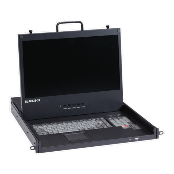
NEED HELP? LEAVE THE TECH TO US LIVE 24/7 CHAPTER 2: OVERVIEW TECHNICAL SUPPORT 1.877.877.2269 2. OVERVIEW 2.1 INTRODUCTION The ServView HD KVM Tray combines a 17.3” LED-backlit display, keyboard, and touchpad in only 1U of valuable rack space. With built-in VGA, DisplayPort, and HDMI interfaces, it can support a variety of KVM switches for multiple server management. -
Page 6: Hardware Description
NEED HELP? LEAVE THE TECH TO US LIVE 24/7 CHAPTER 2: OVERVIEW TECHNICAL SUPPORT 1.877.877.2269 2.3 HARDWARE DESCRIPTION 2.3.1 FRONT VIEW FIGURE 2-1. FRONT VIEW TABLE 2-1. FRONT-PANEL COMPONENTS DESCRIPTION NUMBER COMPONENT Latch Lock Lock or unlock the LCD console drawer when it is closed. Upper Handle Pull out/ Push in the LCD console drawer. -
Page 7: Back View
NEED HELP? LEAVE THE TECH TO US LIVE 24/7 CHAPTER 2: OVERVIEW TECHNICAL SUPPORT 1.877.877.2269 2.3.2 BACK VIEW FIGURE 2-2. BACK VIEW TABLE 2-2. BACK-PANEL COMPONENTS DESCRIPTION NUMBER COMPONENT Grounding Terminal The grounding wire (used to ground the unit) attaches here. Power Socket This is a standard 3 prong AC power socket. -
Page 8: Open View
NEED HELP? LEAVE THE TECH TO US LIVE 24/7 CHAPTER 2: OVERVIEW TECHNICAL SUPPORT 1.877.877.2269 2.3.3 OPEN VIEW FIGURE 2-3. OPEN VIEW TABLE 2-3. OPEN VIEW COMPONENTS DESCRIPTION NUMBER COMPONENT Keyboard Standard 104-key keyboard Touchpad Standard mouse touchpad LCD Display Display the OSD and the source devices’... -
Page 9: Rackmount Procedure
NEED HELP? LEAVE THE TECH TO US LIVE 24/7 CHAPTER 3: RACKMOUNT PROCEDURE TECHNICAL SUPPORT 1.877.877.2269 3. RACKMOUNT PROCEDURE Before Installation: Š The surface for placing and fixing this device should be stable and level or mounted into a suitable cabinet. Š... - Page 10 NEED HELP? LEAVE THE TECH TO US LIVE 24/7 CHAPTER 3: RACKMOUNT PROCEDURE TECHNICAL SUPPORT 1.877.877.2269 2. Fasten the brackets to the rack pillars securely with the screws and cage nuts. FIGURE 3-3. SECURE WITH HARDWARE 3. Slide the LCD console drawer between the brackets. FIGURE 3-4.
-
Page 11: Using The Servview Hd Kvm Tray
NEED HELP? LEAVE THE TECH TO US LIVE 24/7 CHAPTER 4: USING THE SERVVIEW HD KVM TRAY TECHNICAL SUPPORT 1.877.877.2269 4. USING THE SERVVIEW HD KVM TRAY After finishing the rack mounting, you can start to use the ServView HD KVM Tray. NOTES: Do not place any object or lean on the LCD console drawer when it is pulled out. -
Page 12: Closing The Lcd Console Drawer
NEED HELP? LEAVE THE TECH TO US LIVE 24/7 CHAPTER 4: USING THE SERVVIEW HD KVM TRAY TECHNICAL SUPPORT 1.877.877.2269 3. Flip up the LCD console drawer. FIGURE 4-3. FLIP UP DRAWER 4.2 CLOSING THE LCD CONSOLE DRAWER 1. Fold the LCD console drawer. 2. -
Page 13: Connecting A Server Or Kvm Switch
NEED HELP? LEAVE THE TECH TO US LIVE 24/7 CHAPTER 4: USING THE SERVVIEW HD KVM TRAY TECHNICAL SUPPORT 1.877.877.2269 4.3 CONNECTING A SERVER OR KVM SWITCH Follow the installation drawings and instructions below for standard connections. After the installation is completed, the LCD console drawer can be powered on. -
Page 14: Connecting A Keyboard/Monitor/Mouse Or Kvm Extender
NEED HELP? LEAVE THE TECH TO US LIVE 24/7 CHAPTER 4: USING THE SERVVIEW HD KVM TRAY TECHNICAL SUPPORT 1.877.877.2269 4.4 CONNECTING A KEYBOARD/MONITOR/MOUSE OR KVM EXTENDER NOTE: Both the LCD console drawer and the keyboard and mouse connected to the “local console” can operate the equipment. 4.4.1 CONNECTING A KEYBOARD/MONITOR/MOUSE FIGURE 4-7 CONNECT KEYBOARD/MONITOR/MOUSE 4.4.2 CONNECTING A KVM EXTENDER... -
Page 15: Connecting An External Usb Device
NEED HELP? LEAVE THE TECH TO US LIVE 24/7 CHAPTER 4: USING THE SERVVIEW HD KVM TRAY TECHNICAL SUPPORT 1.877.877.2269 4.5 CONNECTING AN EXTERNAL USB DEVICE Connect any USB device to the front panel USB-A port of the LCD console drawer. NOTE: The server should detect the connection of the external USB device. -
Page 16: On-Screen Display Interface
NEED HELP? LEAVE THE TECH TO US LIVE 24/7 CHAPTER 5: ON-SCREEN DISPLAY INTERFACE TECHNICAL SUPPORT 1.877.877.2269 5. ON-SCREEN DISPLAY INTERFACE 5.1 OSD BUTTONS FIGURE 5-1 OSD INDICATOR/BUTTONS TABLE 5-1. OSD BUTTONS DESCRIPTION NUMBER COMPONENT The LED indicator lamp indicates the current power status. •... -
Page 17: Osd Menus
NEED HELP? LEAVE THE TECH TO US LIVE 24/7 CHAPTER 5: ON-SCREEN DISPLAY INTERFACE TECHNICAL SUPPORT 1.877.877.2269 5.2 OSD MENUS An explanation of the OSD adjustment settings is next. FIGURE 5-2 PICTURE MENU TABLE 5-2. PICTURE MENU COMPONENTS EXPLANATION PICTURE NO. SETTING Brightness Make the screen image brighter or darker. - Page 18 NEED HELP? LEAVE THE TECH TO US LIVE 24/7 CHAPTER 5: ON-SCREEN DISPLAY INTERFACE TECHNICAL SUPPORT 1.877.877.2269 FIGURE 5-3 COLOR MENU TABLE 5-3. COLOR MENU COMPONENTS EXPLANATION COLOR NO. SETTING Color Effect Choose the Color Effect. Saturation Adjusts the Saturation setting. Gamma On/off the Gamma function.
- Page 19 NEED HELP? LEAVE THE TECH TO US LIVE 24/7 CHAPTER 5: ON-SCREEN DISPLAY INTERFACE TECHNICAL SUPPORT 1.877.877.2269 FIGURE 5-5 OSD MENU TABLE 5-5. OSD MENU COMPONENTS EXPLANATION OSD NO. SETTING Language Selects the language that the OSD displays its menus in. Menu Time Set the time duration in seconds for which the OSD remains visible after the last button is pressed.
- Page 20 NEED HELP? LEAVE THE TECH TO US LIVE 24/7 CHAPTER 5: ON-SCREEN DISPLAY INTERFACE TECHNICAL SUPPORT 1.877.877.2269 TABLE 5-6. DISPLAY MENU COMPONENTS EXPLANATION DISPLAY NO. SETTING Adjust the clock to synchronize the sampling clock of the display with the pixel clock of the connected Clock equipment.
-
Page 21: Fcc Class A Statement
NEED HELP? LEAVE THE TECH TO US LIVE 24/7 APPENDIX A: REGULATORY INFORMATION TECHNICAL SUPPORT 1.877.877.2269 A.1 FCC CLASS A STATEMENT This equipment generates, uses, and can radiate radio-frequency energy, and if not installed and used properly, that is, in strict accordance with the manufacturer’s instructions, may cause interference to radio communication. It has been tested and found to comply with the limits for a Class A computing device in accordance with the specifications in Subpart B of Part 15 of FCC rules, which are designed to provide reasonable protection against such interference when the equipment is operated in a commercial environment. -
Page 22: Nom Statement
NEED HELP? LEAVE THE TECH TO US LIVE 24/7 APPENDIX A: REGULATORY INFORMATION TECHNICAL SUPPORT 1.877.877.2269 A.2 NOM STATEMENT 1. Todas las instrucciones de seguridad y operación deberán ser leídas antes de que el aparato eléctrico sea operado. 2. Las instrucciones de seguridad y operación deberán ser guardadas para referencia futura. 3. -
Page 23: Disclaimer
B.1 DISCLAIMER Black Box Corporation shall not be liable for damages of any kind, including, but not limited to, punitive, consequential or cost of cover damages, resulting from any errors in the product information or specifications set forth in this document and Black Box Corporation may revise this document at any time without notice. - Page 24 NEED HELP? LEAVE THE TECH TO US LIVE 24/7 TECHNICAL SUPPORT 1.877.877.2269 © COPYRIGHT 2021. BLACK BOX CORPORATION. ALL RIGHTS RESERVED. K VT617A_USER_REV1.PDF...
Need help?
Do you have a question about the SERVVIEW KVT617A-US and is the answer not in the manual?
Questions and answers