Table of Contents
Advertisement
Quick Links
Request
Please make sure that this instruction manual is delivered to the end user.
Preface
This instruction manual is written for people involved in DSS Series wiring, installation, operation, and daily maintenance.
This instruction manual describes precautions, mounting methods, wiring, function descriptions, and operating methods for
handling the DSS Series, so always keep it in a convenient location when handling the DSS Series.
Also, be sure to observe the contents described in this instruction manual.
Safety precautions, precautions regarding equipment and facility damage, additional explanations, and provisos are listed
under the following headings.
1. Safety Precautions ···················································································································· 2
2. Introduction ······························································································································ 3
2-1. Check before use ··································································································································· 3
2-2. Precautions for use ································································································································· 6
3. Usage Location (Environment) ····································································································· 7
4. Name of each part ····················································································································· 7
5. External dimensions ·················································································································· 7
6. Wiring ····································································································································· 8
6-1. Measurement input wiring ························································································································ 8
6-2. Power supply and load wiring ···················································································································· 8
6-3. Wiring of optional and grounding terminals etc. ····························································································· 9
6-4. Terminal Layout for Different Installed Controller Specifications ········································································ 9
6-5. Terminal layout explanation ···················································································································· 10
7. Operation / Adjustment ············································································································· 10
7-1. Operation confirmation ·························································································································· 10
7-2. PID Adjustment ···································································································································· 10
8. Control Method and Circuit Configuration ····················································································· 11
8-1. Thyristor control system output characteristics ····························································································· 11
8-2. Internal circuit configuration diagram ········································································································· 11
9. Troubleshooting ······················································································································ 12
10. Specifications ························································································································· 12
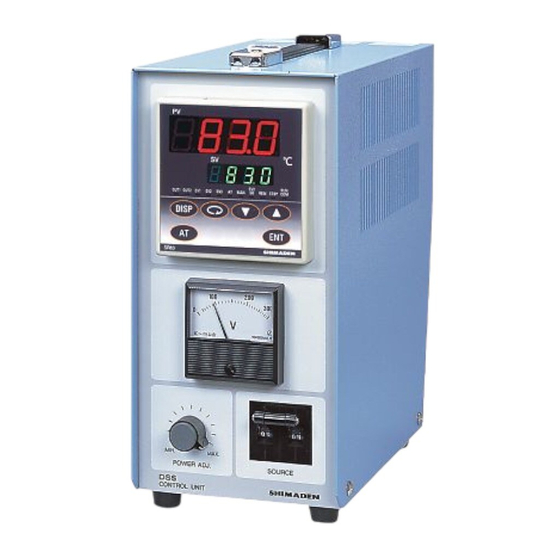
Desktop-Type Temperature Control Device
Instruction Manual
Thank you for purchasing this Shimaden product.
Make sure that the product you are looking for is exactly what you
want, and read this instruction manual carefully so that you fully
understood it before use.
Table of Contents
DSS Series
1
DSSF-1DE
May. 2024
Advertisement
Table of Contents

Related Manuals for Shimaden DSS Series


Summary of Contents for Shimaden DSS Series
-
Page 1: Table Of Contents
Please make sure that this instruction manual is delivered to the end user. Preface This instruction manual is written for people involved in DSS Series wiring, installation, operation, and daily maintenance. This instruction manual describes precautions, mounting methods, wiring, function descriptions, and operating methods for handling the DSS Series, so always keep it in a convenient location when handling the DSS Series. -
Page 2: Safety Precautions
To ensure safety and maintain the functions of this device, do not disassemble this device. If this device must be • disassembled for replacement or repair, contact your dealer. • This instruction manual is common to the DSS Series. Refer to the instruction manual for each controller for details on how to handle the installed controllers. -
Page 3: Introduction
Current 4 to 20 mA DC Load resistance: 300Ω max Voltage 0 to 10 V DC Load current:: 2mA max None 11. Communication function RS-485 Shimaden standard protocol RS-232C None With 12. External input control signal control input 2 points Non-voltage contact... - Page 4 Current 4 to 20 mA DC Load resistance: 300Ω max. Voltage 0 to 10 V DC Load current: 2mA max. None 10. Communication (* Cannot be selected simultaneously with the RS-485 Shimaden standard protocol / status output) MODBUS communication protocol RS-232C None 11.
- Page 5 Current 4 to 20 mA DC Load resistance: 300Ω max. Voltage 0 to 10 V DC Load current: 2mA max. For sensor power supply 24 V DC 25 mA None 11. Communication function RS-485 Shimaden standard protocol / MODBUS communication protocol RS-232C None 12. Remarks With...
-
Page 6: Precautions For Use
9. Analog output 2/Power supply for sensor Voltage 0 to 10 V DC Load current: 2mA max. For sensor power supply 24 V DC 25 mA None 10. Communication function RS-485 Shimaden standard protocol / MODBUS communication protocol RS-232C None 11. Remarks With 5). Accessories check... -
Page 7: Usage Location (Environment)
3. Usage Location (Environment) CAUTION Do not use the product in the following locations. Doing so may cause failure or fire as a result of damage to the product. 1). Locations where flammable gas, corrosive gas, oil smoke, or dust that damages insulation, etc. is generated or present in a large quantity. -
Page 8: Wiring
6. Wiring WARNING • Do not turn on the device when wiring. • Be sure to wire the ground terminal ( ). If you turn on the device without grounding, you may receive an electric shock. • Do not touch the terminals after wiring or other charged parts while the power is on. 6-1. -
Page 9: Wiring Of Optional And Grounding Terminals Etc
6-3. Wiring of optional and grounding terminals etc. 1). Optional terminals, etc. (screw diameter M4, terminal width 8.3 mm, manufacturer recommended tightening torque 1.2 N m) To avoid the effects of noise, route the input/output signal lines of the control input/output terminals away from high-power circuit wiring such as power circuits. -
Page 10: Terminal Layout Explanation
6-5. Terminal layout explanation □ Wiring example SR83: Event output + remote input + communication interface usage example EVENT RS-232C or RS-485 SOURCE LOAD AL1 AL2 Power supply Ground AC 100 V to 120 V or 200 V to 240 V Programmable setting device, etc. -
Page 11: Control Method And Circuit Configuration
8. Control Method and Circuit Configuration 8-1. Thyristor control system output characteristics Item Output waveform (reference diagram) 10% output 50% output 90% output Control method Phase angle control method (P) 8-2. Internal circuit configuration diagram Power adjuster Power switch and circuit protector Thyristor type power regulator... -
Page 12: Troubleshooting
: Installed controller FP23A: Approximately 4.4 kg for both 20 A and 30 A * With regard to the technical details of products, please contact your nearest Shimaden dealer. The contents of this manual are subject to change without notice.
Need help?
Do you have a question about the DSS Series and is the answer not in the manual?
Questions and answers