Table of Contents
Advertisement
Thank you for purchasing a Shimaden product. Please check that the delivered product is the correct item
you ordered. Please do not begin operating this product before you read this instruction manual thoroughly
and understand its contents.
"Notice"
Please ensure that this instruction manual is given to the final user of the instrument.
"Preface"
This instruction manual is meant for those who will be involved in the wiring, installation, operation and routine
maintenance of the FP93. It describes matters to be attended to in handling the FP93, how to install it, wiring, its
functions and operating procedure. Keep this manual at the work site while handling the instrument and follow the
guidance provided herein.
FP93
Program Controller
Instruction Manual
- 1 -
FP93F-1HE
Jan. 2018
Advertisement
Table of Contents

Subscribe to Our Youtube Channel
Related Manuals for Shimaden FP93


Summary of Contents for Shimaden FP93
- Page 1 This instruction manual is meant for those who will be involved in the wiring, installation, operation and routine maintenance of the FP93. It describes matters to be attended to in handling the FP93, how to install it, wiring, its functions and operating procedure. Keep this manual at the work site while handling the instrument and follow the guidance provided herein.
-
Page 2: Table Of Contents
Contents (3) Setting FIX No..............17 1. Safety Rules ..............3 (4) Setting FIX Event Action Point ........17 5-9. Explanation of screen Group 4 and Setting ..18 2. Introduction ..............4 (1) Setting Outputs of PID Nos. 1 – 6 ........18 2-1. -
Page 3: Safety Rules
WARNING The FP93 Program Controller are control instruments designed for industrial use to control temperature, humidity and other physical values. Avoid using it for control of devices which may seriously affect the human life. When used, adequate and effective safety measures must be taken. -
Page 4: Introduction
Example of model codes: FP93 8 Y 90 1 3 5 0 1. Name of produuct FP93 2. Input 8 : Multi-input: thermocouple, R.T.D., voltage (mV), Voltage (V) 4 : Current (mA)(attached with an extermal resistor 250 ) 9 : With remarks 3. -
Page 5: Mounting
As the instrument is provided with pawls for fixing, just press it firmly from the front of the panel. The case is fixed to the panel by means of the pawls. The FP93 is designed as a panel-mounting model. Never use it without mounting on the panel. 3-3. External Dimensions and Panel Cutout... -
Page 6: Terminal Layout
3-5. Terminal Layout (Follow the terminal layout and terminal arrangement table shown below in your wiring operation.) 3-6. Terminal Arrangement Table Name of terminal Description / Code Terminal No. Power supply 100 - 240V AC/24V AC: L, 24V DC: + 100 - 240V AC/24V AC: N, 24V DC: - Protective conductor Protective grounding... -
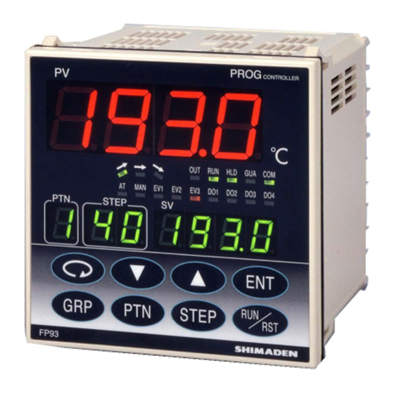
Page 7: Names And Functions Of Parts On Front Panel
4. Names and Functions of Parts on Front Panel Name Function Measured value (PV) (1) Present measured value is displayed in the screen group 0. (red) (2) Type of parameter is shown on each parameter screen. display Action display (green) Ascending action lamp •... - Page 8 Name Function Operating keys (parameter) key • Pressing this key on any screen calls the next screen onto display. • Pressing this key continuously for 3 seconds calls the initial screen of screen group 5. (up) key • Used to increase a numerical value on a numerical value setting screen. •...
-
Page 9: Explanation Of Screens And Setting
5. Explanation of Screens and Setting 5-1. Parameter Flow NOTE: Four kinds of frame lines signify the following. The figure on the left of each frame represents screen No. Screens regularly shown by key Screens shown when appropriate option is added or operation and other means. - Page 10 - 10 -...
- Page 11 - 11 -...
- Page 12 Screen Group 5 Initial setting screen group Screen Initial screen 5-23 screen The number of patterns setting 5-23 Event 2 hysteresis setting Time unit setting 5-24 Event 2 standby action setting With/without power failure compensation setting 5-25 Event 3 type setting Input abnormality mode setting 5-26 Event 3 hysteresis setting...
-
Page 13: Application Of Power And Display Of Initial Screen
5-2. Application of Power and Display of Initial Screen When power is applied, the initial screen and two screens are displayed successively, each for about 1 second as shown below. Then the basic screen is displayed. 5-3. How to Change Screens (1) How to Change Screen Groups 0 - 5 •... -
Page 14: How To Change Screen In Screen Group 3
(3) How to Change Screen in Screen Group 3 Every time the key is pressed, the next screen is called, and the basic screen is called from the last screen. Pressing the calls the preceding screen. (4) How to Change Set Values (Data) To change data on a screen which is called by pressing the key, use the key, and register the changed data by pressing the... -
Page 15: Explanation Of Screen Group 0 And Setting
Measured value display (PV display) Target set value display (SV display) (2) Setting ADV Execution Pattern No. display (PTN display) 0-6 ADV execution setting screen Step No. display (STP display) To 1-0 screen 5-5. Explanation of Screen Group 0 and Setting 0-0 Basic screen Initial value : OFF... -
Page 16: Setting Time Signal
(3) Setting Time Signal 1-10 Time signal 2 (TS2) OFF time setting screen 1-3 Time signal 1 (TS1) ON step setting screen To 1-1 (pattern 2) screen To 1-1 (pattern 2) screen To 2-1 (step 1) screen To 2-1 (step 1) screen To 1-0 (pattern 1) screen To 1-0 (pattern 1) screen Initial value: 00.00... -
Page 17: Setting Guarantee Soak Zone
(7) Setting Guarantee Soak Zone 5-8. Explanation of screen Group 3 and Setting 1-16 Guarantee soak zone setting screen 3-0 Initial screen To 1-1 (pattern 2) screen To 4-0 screen To 2-1 (step 1) screen To 1-0 (pattern 1) screen representing FIX mode is shown on PTN display. -
Page 18: Explanation Of Screen Group 4 And Setting
5-9. Explanation of screen Group 4 and Setting 4-8 Higher limit output limiter setting screen Setting of PID Outputs of PID Nos. 1-6 To 4-1 (PID No.2) screen (1) Setting Outputs of PID Nos. 1 – 6 To 4-0 (PID No.1) screen 4-0 Initial screen To 4-0 (PID No.2) screen Initial value: 100.0... -
Page 19: Setting Time Unit
(2) Setting Time Unit 5-8 Input scaling higher limit value setting screen 5-2 Time unit setting screen To 5-0 screen To 5-0 screen Initial value: 100.0 Initial value: Setting range: (Input scale) lower limit value + 10 ~ Setting range: (HM)/ (MS) Lower limit value + 5000 digits... -
Page 20: Setting External Control Input
Table of Event Type Codes 5-15 SV limiter higher limit value setting screen Code Type of event To 5-0 screen None Higher limit deviation Lower limit deviation Outside higher/lower limit deviations Initial value: Higher limit value of measuring range Within higher/lower limit deviations Setting range: + 1 count ~ Higher limit of Higher limit absolute value... -
Page 21: Setting Status Output (Do)
Setting range : (Shim), (Asc), 5-30 Status output 3 (DO3) action code setting screen (RTU) To 5-0 screen Shim: Shimaden standard mode asc: MODBUS ASCII mode rtu: MODBUS RTU mode Initial value: NON Select either one of the communication protocols. Setting range: The same as the 5-28 screen except DO1 changed to DO3. -
Page 22: Setting Keylock
Setting range: 8 types in the following table Setting range: COM1, COM2 Selects type of communication mode. A communication data format is set. Set to COM1 if you want to enable key operation while writing by communication. Data Stop Shimaden MODBUS/ MODBUS/ Selection Parity length bits standard... -
Page 23: Operation And Functions
6 Operation and Functions 6-1. Using FIX Mode FIX: Adjustment function without using the program function. Pressing the key on the 3-1 FIX ON/OFF screen turns OFF shown on the target value (SV) display to ON and the decimal point of the rightmost digit blinks. -
Page 24: Pid Action
Release of AT in the Middle To release AT in the middle, select OFF on the AT execution setting screen by the use of key and press the key. NOTE: In case AT is released in the middle, PID values are not changed. Reasons Why AT Does Not Function 1) Control output is in manual mode. -
Page 25: Zone Pid
6-9. Zone PID The PID control of this instrument allows you to select and set the zone method. In the zone PID control, a measuring range is divided into three types maximum, and control is carried out with PID No. which is selected automatically from an SV value set for each step. -
Page 26: Events
6-11. Events Deviation Alarm An alarm action point is set by a deviation of measured value (PV) from target set value (SV). For instance, to activate an alarm when measured value (PV) reaches 30 ˚C against SV value at 20 ˚C, higher limit deviation alarm is set at 10 ˚C. -
Page 27: Time Signal
6-15. Time Signal Time signal: Event output and status output can be produced for a designated period of time. Two points per pattern are equipped and ON step, OFF step, ON time and OFF time can be set individually. Time signal functions under the following conditions: is set as status output of event output. -
Page 28: Status (Do) Output
R.T.D. Higher limit side scaleover Ambient temperature of Reduce ambient temperature to the level of cold junction (CJ) of FP93 has exceeded 80°C. provided in the environment conditions. (CJHH) thermocouple input In case ambient temperature has not exceeded 80°C, examine the instrument. -
Page 29: Record Of Parameter Setting
8. Record of Parameter Setting (For convenience sake, recording set values and selected items is recommended.) The initial values are of Code 05 (K). Screen No. Parameter (Item) / Screen Initial value Setting/Selection Remarks Basic screen Output monitor Step remaining time Pattern execution number monitor PID No. - Page 30 Screen No. Parameter (Item) / Screen Initial value Setting/Selection Remarks PID No. 2 Initial screen Pid. PID P PID hysteresis digit PID I PID D PID MR PID SF PID lower limit o_L. PID higher limit o_H. PID No. 3 Initial screen Pid.
- Page 31 Screen No. Parameter (Item) / Screen Initial value Setting/Selection Remarks Initial screen init. Pattern No. designation Ptn. Time designation tmUn. With/without power failure compensation SAVE. ( Input abnormality code Measuring range rAnG. Input unit Unit. Input scale lower limit value Sc_L.
- Page 32 100% Pattern No. Start SV The number of steps TS1 ON step TS1 ON time TS1 OFF step TS1 OFF time TS2 ON step TS2 ON time TS2 OFF step TS2 OFF time EV1 setting EV2 setting EV3 setting The number of pattern executions Guarantee soak PV start...
-
Page 33: Specifications
9. Specifications Display Display means Digital display : PV Red 7 segments LED 4 digits : SV Green 7 segments LED 4 digits : PTN Green 7 segments LED 1 digit : STEP Green 7 segments LED 2 digits Status display : OUT Green LED lamp indication : EV1 - 3 (3 points) Orange LED lamp indication... - Page 34 Communication delay : 1 - 100 (0.512msec/unit) Communication memory mode : Selectable from EEP, rAm and r_E Communication protocol : Shimaden standard mode Data format : 7E1, 7E2, 7N1, 7N2, 8E1, 8E2, 8N1, 8N2 Control code : STX_ETX_CR, STX_ETX_CRLF, @_:_CR...
- Page 35 Analog output (option) Number of output points Type of analog output : Selectable from measured value, target value (SV in execution) and control output Output specification/rating : Current 4 - 20mA DC (Maximum load resistance 300 ) Voltage 0 - 10V DC (Maximum load resistance 2mA) 0 - 10mV DC (Output resistance 10 ) Output accuracy : ±0.3% FS (Comprehensive accuracy when measured value is output ±0.6% FS )
- Page 36 PRINTED IN JAPAN - 36 -...
Need help?
Do you have a question about the FP93 and is the answer not in the manual?
Questions and answers