
Related Manuals for Horizon Hobby Mystique RES 2.9m ARF


Summary of Contents for Horizon Hobby Mystique RES 2.9m ARF
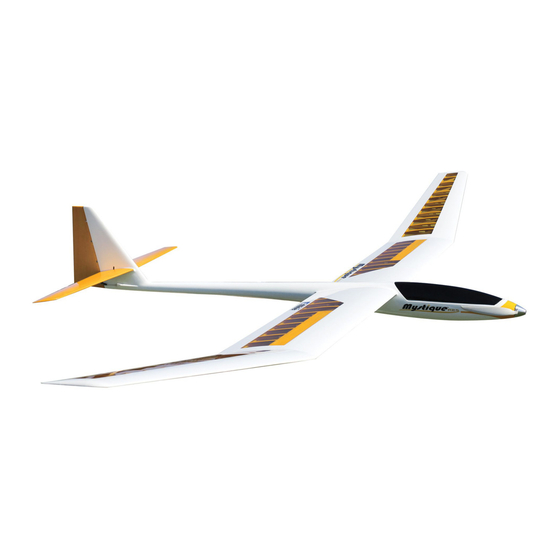
- Page 1 Mystique RES 2.9m ARF ™ ALMOST-READY-TO-FLY Instruction Manual Bedienungsanleitung Manuale di Istruzioni...
-
Page 2: Safety Warnings And Precautions
Do not use with incompatible components or alter this product in any way outside of the instructions This kit includes small parts and should not be left provided by Horizon Hobby, Inc. This manual contains instructions for safety, operation and maintenance. It is unattended near children as choking and serious injury essential to read and follow all the instructions and warnings in the manual, prior to assembly, setup or use, in could result. -
Page 3: Warnungen Und Sicherheit-Svorkehrungen
Erwachsenen. Verwenden Sie das Produkt nicht mit inkompatiblen Komponenten oder verändern es in Folgen Sie immer den Herstelleranweisungen bei jedweder Art ausserhalb der von Horizon Hobby, Inc. vorgegebenen Anweisungen. Diese Bedienungsanleitung dem Gebrauch oder Entsorgung von Akkus. Falsche Behandlung von LiPo Akkus kann zu Feuer mit enthält Anweisungen für Sicherheit, Betrieb und Wartung. - Page 4 Non usare componenti non Piccole parti compatibili o alterare il prodotto in nessuna maniera al di fuori delle istruzioni fornite da Horizon Hobby, Inc. Questo manuale contiene le istruzioni per un funzionamento e una manutenzione sicuri. È fondamentale leggere e seguire Questo kit comprende delle parti di piccole dimensioni e non lo si può...
-
Page 5: Before Starting Assembly
before starting asseMbly Vor deM ZUsaMMenbaU PriMa di iniZiare il Montaggio • Remove parts from bag. • Entnehmen Sie zur Überprüfung jedes Teil der Verpackung. • Togliere tutti i pezzi dalla scatola. • Inspect fuselage, wing panels, rudder and stabilator for damage. • Überprüfen Sie den Rumpf, Tragflächen, Seiten- und Höhenruder auf • Verificare che la fusoliera, l’ala e i piani di coda non siano danneggiati. - Page 6 speciFications•speziFikationen• large parts layout•bauteile (ohne kleinteile)• sPeCifiChe sCheMa dei CoMPonenti grandi 114 in (2.90 m) 1030 sq in (66.5 dm2) 58.5 in (1.48 m) 4.85–5.00 lb (2.20–2.25 kg) Electric Power: Power 25 Brushless, 1000Kv Elektro Antrieb: Power 25 Brushless, 1000Kv Motore elettrico Power: 25 Brushless, 1000Kv 4-channel (or greater) with 4 servos 4-Kanal (oder größer) mit 4-Servos...
- Page 7 replacement parts•ersatzteile•ricambi Part english deutsch italiano EFL491501 Right Wing Panel Tragfläche rechts Semiala destra EFL491502 Left Wing Panel Tragfläche links Semiala sinistra EFL491503 Fuselage Rumpf Fusoliera EFL491504 Rudder Seitenruder Timone EFL491505 Stabilator Höhenruder Stabilizzatore EFL491508 Wing Rod Flächenverbinder Baionetta ala EFL491509 Stabilator Rods Höhenruderverbinder...
- Page 8 required adhesiVes•erForderliche klebstoFFe•adesiVi necessari Part english deutsch italiano PAAPT03 Medium CA Sekundenkleber mittel Medio CA PAAPT09 Thin CA Sekundenkleber dünnflüssig Sottile CA PAAPT42 Threadlock Schraubensicherungslack Frenafiletti PAAPT35 15-Minute Epoxy 15 Minuten Epoxy Colla epoxy 15 minuti Glue stick Klebestift Stick colla required tools•benötigtes werkzeug•attrezzi necessari english deutsch...
- Page 9 assembly symbol guide•montage symbole•guida ai simboli di assemblaggio Apply threadlock Ensure free rotation Use medium CA Use a pencil Schraubensicherungslack verwenden Rotation sicherstellen Mittelflüssigen Verwenden Sie einen Bleistift Sekundenkleber verwenden Applicare fuido threadlock Assicurarsi rotazione libera Usare una matita Usare colla ciano acrilica media Assemble right and left Push tightly Use thin CA...
- Page 10 rudder control horn installation•einbau der seitenruderhörner•installazione squadretta timone hinging the rudder• seitenrudermontage• inCernierare il tiMone Use sandpaper to lightly sand the bottom of the control Place low-tack tape so it is spaced 1/32 inch (1mm) horn where it fits into the rudder. Remove any dirt from the base of the control horn.
- Page 11 The following steps outline the installation of the Î rudder hinges. Their alignment must be correct for the rudder to move through its full range of motion. Do not use any epoxy on the hinges until instructed. Î...
- Page 12 Fit the rudder to the fin using the hinges. The gap between the front edge (leading edge) of the rudder and fin must be as small as possible. Fit the epoxy-covered hinges into the rudder. Make sure they are aligned as described, then use a paper towel Passen Sie das Ruder an die Finne mit den drei and isopropyl alcohol to remove any excess epoxy that...
- Page 13 ReceiveR and SeRvo inStallation•empfängeR und SeRvoeinbau• inStallazione del ricevitore e del Servo There are two possible radio configurations for the Option 2: In this setup the throttle is activated by the Mystique RES. The first is more commonplace to throttle stick, allowing the model to be flown at various motorized sailplane, or powered sailplane operation, throttle settings in the same manner as a powered...
- Page 14 1 Rudder•Seitenruder• Timone Stabilator•Höhenruder• Elevatore Install the servo grommets and brass eyelets in the servos. Plug the rudder servo into the aileron port of the receiver. With the radio system on, make sure the programming has been cleared (if using a computer radio) and that the aileron stick and trim are centered.
- Page 15 3 4 5 Repeat the steps for installing the rudder servo to secure the stabilator servo in the fuselage. Fit the rudder servo into the radio tray inside the Remove the servo from the fuselage. Use a pin vise Place the rudder servo back into the fuselage with Wiederholen Sie die Schritte für den Einbau des fuselage.
- Page 16 Plug the rudder servo into the aileron port and stabilator Place the receiver in the fuselage. Route the lead(s) for servo into the elevator port of the receiver. Plug a the spoilers under the radio tray and through the holes Y-harness into the throttle (or flap) channel of the behind the servos.
- Page 17 rudder linkage installation•montage seitenruderanlenkung• installaZione del CoMando Per il tiMone 1/2 inch (13mm) Remove the servo horn from the rudder servo. Attach the clevis to the servo horn as shown in the photo. Thread a nut, then a clevis on the brass fitting that has Entfernen Sie das Servohorn vom Seitenruderservo.
- Page 18 Place the rudder servo arm back on the rudder servo. Make sure to use the radio system to verify the servo arm is installed perpendicular to the servo centerline as Align the rudder with the fuselage centerline. Use care With the radio system on and the rudder servo and outlined earlier in this manual.
- Page 19 stabilator linkage installation•montage höhenruderanlenkung• installaZione del CoMando Per l’eleVatore While the radio is still on, check to make sure the rudder Remove the servo horn from the stabilator servo. Attach is centered when the rudder servo is centered. If not, the clevis to the servo horn as shown in the photo.
- Page 20 Use a glue stick (available at a craft store or discount Slide the larger and smaller stabilator rods into the store) to apply a small amount of adhesive to the first stabilator. They will slide easily, so don’t force them any 1 inch (25mm) of the larger carbon stabilator joiner rod.
- Page 21 Use pliers to bend the pushrod wire 90 degrees at the mark made previously. Use side cutters to trim the wire so 1/4 inch (6mm) of wire extends beyond the bend. Center the stabilator and stabilator servo, then mark Insert the wire through the hole in the stabilator Once the pushrod wire has been secured, place the the pushrod where it crosses the hole in the stabilator...
- Page 22 spoiler serVo installation•einbau der störklappenserVos•installazione del serVo spoiler When the spoilers are deployed, lift produced by Î the wing will be reduced, which increases model’s sink rate. Some amount of up elevator may be required with spoiler use to control the attitude of the model. Sind die Störklappen ausgefahren Î...
- Page 23 when using the flap channel of your radio system. Make sure to center the spoiler servo by Î setting the switch in the center position if using a transmitter with a three-position switch. If your radio has a two-position switch, temporarily use a different channel such as the rudder to center the servo.
- Page 24 The servo can be removed from the Î cover if necessary by slipping a thin ruler or screwdriver between the servo and cover and prying the servo from the cover. Î Das Servo kann von der Abdeckung entfernt werden in dem Sie ein dünnes Lineal oder Schraubendreher zwischen Servo und Abdeckung schieben und das Servo von der Abdeckung trennen.
- Page 25 Assemble the spoiler linkage using two nuts, two Use a pin vise and 1/16-inch (1.5mm) drill bit to enlarge Connect the spoiler linkage to the hole enlarged in the clevises and the 2mm x 40mm threaded rod. Make the hole in the servo arm.
- Page 26 Use the string to pull the extension through the wing. Connect the linkage to the spoiler control horn. The Plug the spoiler servo into the throttle (or flap or AUX The tape can be removed once the extension is through servo may be rotated and/or positioned to allow for the channel) of your radio system.
- Page 27 M2 x 8 M2 x 8 Once the linkage length has been set, tighten the nuts Thread a spoiler cover mounting screw into the four Apply a small amount of thin CA into each of the holes. Secure the spoiler servo cover using the four screws.
- Page 28 motor installation•einbau des motors•installazione del motore If you are building your model as a pure sailplane, you can skip to Î the section “Sailplane Completion” located on Page 31. Sollten Sie ihr Modell als reines Segelflugzeug bauen können Sie diesen Arbeitsschritt Î...
- Page 29 Route the battery lead from the speed control under the radio tray and through the slot so the battery can be connected. Mount the switch on the opposite side of the fuselage from the battery lead and secure it using a small piece of hook and loop tape.
- Page 30 Using the remaining portion of the hook and loop tape, Inspect the propeller yoke (EFLP14080FA). When attach the loop portion to the bottom of the battery. Do installing the propeller blades, face the notches in the not cover safety warnings with hook and loop tape. Place yoke towards the front of the aircraft.
- Page 31 sailplane completion•montage segelFlugzeug•completa mento dell’aliante If you have built your model as an Î electric sailplane, you can skip to the section “Canopy Installation” located on Page 32. Haben Sie ihr Modell als Segelflugzeug Î gebaut können Sie zum dem Kapitel Montage der Kabinenhaube springen.
- Page 32 canopy installation• montage der kabinenhaube• installaZione della CaPottina Fill the nose cone with small steel shot or Deluxe Materials Liquid Gravity (DLMBD38). Use 15-minute epoxy to Secure the tow hook by threading it into the preinstalled secure the shot so it is secure inside the cone. Allow the epoxy to fully cure before proceeding. Up to 8 ounces (225 blind nut.
- Page 33 Wing inStallation• montage deR tRagflächen• montaggio dell’ala Fit both pins into their respective holes. Use a paper Use a covering iron to seal the covering at the wing root towel and isopropyl alcohol to remove any excess epoxy to the underlying structure.
- Page 34 Slide the wing joiner rod into the socket in the wing. Do Slide the wing joiner rod into the fuselage. When the Once the wing is tight against the fuselage, use white not force the tube into the socket, as it will slide easily. If wing is close to the fuselage, connect the leads for electrical tape along the joint between the wing and it does not, determine why the tube does not fit.
-
Page 35: Center Of Gravity
Center of graVity der schwerpunkt centro di graVita’ (baricentro) An important part of preparing the aircraft for flight is properly balancing the Ein sehr wichtiger Teil in der Flugvorbereitung ist es das Flugzeug richtig Un punto importante per preparare l’aereo al volo è quello di fare un model. -
Page 36: Control Throws
control throws ruderausschläge 1. Turn on the transmitter and receiver of your model. Check the movement of the rudder using the transmitter. 1. Schalten Sie den Sender und Empfänger ihres Modells ein. Prüfen Sie die Seitenruderaussschläge mit dem Sender. When the stick is moved to the right, the rudder should also move right. Reverse the direction of the servo at the Bewegen Sie den Seitenruderstick nach rechts, sollte sich das Ruder auch nach rechts bewegen. -
Page 37: Corse Dei Comandi
Corse dei CoMandi flying yoUr Model Important : Make any trim adjustments in small increments. Large changes can result in abrupt turns, Preflight Trimming 1. Accendere trasmettitore e ricevitore del modello. Controllare i movimenti del timone agendo sul trasmettitore. causing tip stalls and loss of control. Quando lo stick va a destra, anche il timone deve andare a destra. - Page 38 Evening thermals are typically large, warm air masses Wind direction and velocity are also great thermal what to do when you find a thermal in-Flight adjustments for performance and conditions meandering through the sky. They are usually very indicators. Often colder, descending air fills in the hole smooth with soft edges.
-
Page 39: Maximum Lift/Drag (L/D) Speed
minimum sink speed fliegen des Modells Practice smooth control inputs and use the trim lever. Landing This is why you trimmed the model in the test flights Trimmung vor dem Flug Be sure to land into the wind. Due to the high-lifting and then set the mechanical linkages to reflect the trim In our discussion of thermals, we know sink is the your trim levers back to neutral. - Page 40 WICHTIG Die Nachmittagsthermik besteht aus sehr großen Das gleiche gilt wenn der Wind von rechts kommt für Um in der Thermikblase zu bleiben müssen sie ständig : Machen Sie Trimmeinstellungen nur in kleinen Schritten. Grosse Schritte können zu abrupten Mengen bewegter warmer Luft, die normalerweise eine gute Chance dass die Thermikblase zu ihrer Linken steuern.
- Page 41 CoMe far Volare Haben Sie sich mit dem Start und fliegen des Modell Landen vertraut gemacht, können Sie mit dem Üben dieser qUesto Modello Erhöhen des Anstellwinkels Landen Sie immer gegen den Wind. Durch die sehr gute drei Geschwindigkeiten beginnen. Denken Sie daran Trimmaggi prima del volo dass diese Geschwindigkeiten über die Trimmung (oder Gleitleistung des Modells benötigen Sie hier eine große...
- Page 42 si corregge portando il trim del timone dalla parte imparare come si vola con gli alianti. La direzione e la velocità del vento sono degli ottimi cosa fare quando si trova una termica opposta alla virata. indicatori per le termiche. Spesso l’aria discendente più Le termiche del mattino sono molto definite e più...
- Page 43 regolazioni in volo per prestazioni Velocità di minima discesa Una volta che si è imparato bene a controllare il Atterraggio e condizioni modello, si può fare pratica con queste tre velocità. Bisogna ricordare che queste velocità si impostano Accertarsi di essere contro vento. Poiché gli alianti Quando si è...
-
Page 44: Preflight Checklist
preFlight checklist VorFlugkontrolle lista dei Controlli PriMa del Volo • C harge the transmitter, receiver and motor battery for your airplane. • L aden Sie den Sender- ,Empfänger- und Zündakku für Ihr Flugzeug. • C aricare le batterie di trasmettitore, ricevitore e accensione motore Use the recommended charger supplied with your radio system. Follow Verwenden Sie für die RC Anlage bitte das empfohlene Ladegerät. usando i caricabatterie consigliati o forniti con il radiocomando e the instructions provided with the radio. -
Page 45: Daily Flight Checks
daily Flight checks täglicher Flug check Controlli di Volo giornalieri • C heck the battery voltage of the transmitter battery. Do not fly below the • Ü berprüfen Sie die Spannung des Senderakkus. Fliegen Sie nicht wenn die • C ontrollare la tensione della batteria del trasmettitore. Non volare se la manufacturer’s recommended voltage. To do so can crash your aircraft. Spannung unterhalb der vom Hersteller empfohlenen Spannung liegt, da tensione è... -
Page 46: Limited Warranty
Horizon Hobby, Inc. (“Horizon”) warrants to the original HORIZON SHALL NOT BE LIABLE FOR SPECIAL, If this Product needs to be inspected or serviced and Should your service not be covered by purchaser that the product purchased (the “Product”) -
Page 47: Garantie Und Service Informationen
Liegt eine kostenpflichtige Reparatur vor, erstellen enthält Sicherheitshinweise und Vorschriften sowie wurden aus. Rücksendungen durch den Käufer direkt an Exklusive Garantie ¬ Horizon Hobby Inc (Horizon) wir einen Kostenvoranschlag, den wir Ihrem Händler Hinweise für die Wartung und den Betrieb des Horizon oder eine seiner Landesvertretung bedürfen der... -
Page 48: Garanzia
Periodo di garanzia limiti di danno manutenzione e riparazione La garanzia esclusiva - Horizon Hobby, Inc., (Horizon) Horizon non si riterrà responsabile per danni speciali, Se il prodotto deve essere ispezionato o riparato, garantisce che i prodotti acquistati (il “Prodotto”) sono diretti, indiretti o consequenziali;... -
Page 49: Instructions For Disposal Of Weee By Users In The European Union
Harlow, Essex, CM18 7NS, United Kingdom +44 (0) 1279 641 097 Horizon Technischer Service service@horizonhobby.de Christian-Junge-Straße 1 Germany 25337 Elmshorn, Germany Sales: Horizon Hobby GmbH +49 (0) 4121 2655 100 infofrance@horizonhobby.com Service/Parts/Sales: 11 Rue Georges Charpak France Horizon Hobby SAS... -
Page 50: Faa Information
aMa national Model airCraft safety Code b. radio control (rc) effective January 1, 2013 (h) Not operate model aircraft while under the influence 7. Under no circumstances may a pilot or other person of alcohol or while using any drug which could adversely touch a model aircraft in flight while it is still under a. - Page 52 © 2013 Horizon Hobby, Inc. E-flite, Mystique, EC3, Celectra and DSMX are trademarks or registered trademarks of Horizon Hobby, Inc. The Spektrum trademark is used with permission of Bachmann Industries, Inc. All other trademarks, service marks and logos are the property of their respective owners.
Need help?
Do you have a question about the Mystique RES 2.9m ARF and is the answer not in the manual?
Questions and answers