Table of Contents
Advertisement
Quick Links
Advertisement
Table of Contents

Subscribe to Our Youtube Channel
Related Manuals for TPI DC711


Summary of Contents for TPI DC711
- Page 1 Smart Flue Gas Analyser DC711...
-
Page 2: Table Of Contents
Contents Introduction............3 General Overview..........4 Kit Options & Upgrades.........5 Front View............6 Soft Keys...........7 Back View..........8 Bottom View..........9 Top View..........9 Charging........10 Turning On........11 Calibration Information Screens......12 Main Menu...........13 Set Up – Mode & Time..........14 Set Up – CO Alarm Level......15 Set Up – LCD Backlight..........16 Set Up - Auto Power Off.........17 Set Up - Print Header....18 Set Up –... -
Page 3: Introduction
You can connect your View enabled DC711 by searching & choosing it from the List and the DC711 will enter Remote Control Mode. Once connected to TPI View you can control your View enabled DC711 on the app, remotely, and take advantage of all the enhanced features the View app has to offer such as Job Management, GPS tagged Reports and the ability to e-mail and share the reports. -
Page 4: General Overview
Always use the optional oil filter when performing tests on oil burning equipment unless you are using the DC711 with an NO sensor fitted. Do not use the oil filter on the DC711 with NO sensor fitted because the oil filter will filter out Nitric Oxide (NO). -
Page 5: Kit Options & Upgrades
NO sensor addition or replacing the standard CO sensor with a HIGH CO sensor, as well as a Bluetooth Printer and many more essential accessories and consumables. These can be viewed by visiting your local regions websites listed below: - https://www.tpieurope.com/flue-gas-analysers/dc711-flue-gas-analyser/ https://www.testproductsintl.com/gas-detection/combustion-efficiency- analyzers/ https://www.tpicanada.com/gas-detection/combustion-efficiency-analyzers/... -
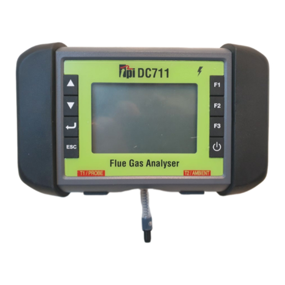
Page 6: Front View
Instrument Overview Front View Protective Rubber End Caps USB “C” Charger Socket Charger Indicator Soft Keys Temperature Sockets Display Gas Inlet & Pressure Ports... -
Page 7: Soft Keys
Enter Key used to select a highlighted menu option and enter that function. Escape key is used to back out of various functions. Function Keys actions will change depending on the screen the DC711 is in. These will be displayed at the bottom of the screen and change accordingly. -
Page 8: Back View
Instrument Overview Back View Magnets Hanging Hook Protective Rubber End Caps Information Labels... -
Page 9: Bottom View
Instrument Overview Bottom View Thermocouple Sockets Pressure Ports Gas Inlet Port Top View USB “C” Charger Socket... -
Page 10: Charging
Basic Analyser Functions Charging Plug the USB “C” cable into the USB “C” charger socket. While charging the charge indicator light will illuminate RED Once charging is complete the charge indicator light will illuminate GREEN... -
Page 11: Turning On
Start Up Screen Please DO NOT have the gas sampling probe attached at this point. The gas sampling probe needs be fitted to the DC711 only at the point where combustion analysis begins. Press and hold the ON/OFF key down for approximately 3 seconds. The DC711 will beep and the initial start-up screen will be displayed. -
Page 12: Calibration Information Screens
Calibration Due Date Messages As the Annual Next Calibration Due Date Approaches or is Overdue one of the following screens may appear: - Choosing “Next” will move you onto the Main Menu Screen as displayed below. Please Note: In the UK, it is a requirement of BS7967 that an FGA is within calibra�on and used in conjunc�on with the manufacturer’s instruc�ons therefore it is NOT recommended that “Next”... -
Page 13: Main Menu
Once the Purge Period has elapsed or “Skip” is pressed the Main Menu will be displayed. If this is the first time you are turning the DC711 on, we suggest you head over to the “Set-Up” section to investigate the options as described below. Press the Up or... -
Page 14: Set Up - Mode & Time
Set Up Menu Mode & Time Entering the Set Up Menu will display the following: - Entering “Mode & Time” will display the following where you can toggle the Display Mode between 7 & 4 Line, adjust the timings for the Let By, Stabilisation &... -
Page 15: Set Up - Co Alarm Level
Set Up Menu CO alarm level Entering “CO alarm level” will display the following where you can toggle the ambient and High CO alarms On & Off, as well as adjusting the default levels to suit your testing requirements Alarm 1 is the ambient CO alarm and Alarm 2 is the High CO alarm for combustion tests. -
Page 16: Set Up - Lcd Backlight
Set Up Menu LCD back light Entering “LCD back light” will display the following where you can adjust the LCD backlight level. Higher levels of backlight will reduce battery life. -
Page 17: Set Up - Auto Power Off
Set Up Menu Auto Power Off Entering “Auto Power off” will display the following where you can disable the Auto power off or change the Auto power off time. -
Page 18: Set Up - Print Header
Set Up Menu Print header Entering “Print header” will display the following where you can add or edit the details that will print out at the top of each report when using the optional A741BT printer and direct printing from the analyzer. -
Page 19: Set Up - Ble Printer
BLE Printer Entering “BLE Printer” will display the following where you can scan and pair available optional A741BT Bluetooth Printer to your DC711. When paired and connected the Printer Icon will display. You only need to pair once. Each time a paired A741BT is switched on it will... -
Page 20: Main Menu
Main Menu Pressing the “Esc” key repeatedly will return you to the Main Menu. Using the Up and Down Arrow Keys will highlight the different functions. Pressing the Enter Key will select the highlighted function. -
Page 21: Flue Gas
Options or the “F3” key to cycle through the various Efficiency options or the “F2 Key” to skip, if displayed. Note: Gross efficiency is used in the USA Once the Purge Period is complete the DC711 will display the Gas Test Screen including NO and NOx (if fitted). - Page 22 “F3” will Hold the readings on the screen and open up the following options: - “F1” will send the Held Readings to the Printer, if connected “F3” will allow you to save the Held Readings in the Memory “F2” will unHold the readings and return to Live Readings...
-
Page 23: Temp/Pressure
Temp/Pressure Press the “Enter” key to bring up the Temperature & Pressure Screen On this screen you can view the Temperature in T1, T2 and the differential between both as well as the Live Pressure. “F1” will Zero the Live Pressure Reading “F2”... -
Page 24: Ambient Co Build Up
Ambient Air CO Build Up Press the “Enter” Key to bring up the CO build up Screen Entering the CO Build Up function will start the Purge Period. During this period you can press the “F2 Key” to skip, if displayed. - Page 25 Once the Purge Period is complete the following screen is displayed where you can start the Ambient Air CO Build Up Test. Press the “F3” Key to change the Storage Address if required. Press the “F2” Key to Start the Test At any time during the test, you can press the “F2”...
-
Page 26: Let By/Tightness Test
Let By/Tightness Test NOTE: The Let By/Tightness test is used mainly in Europe. Press the “Enter” key to bring up the CO build up Screen Press the “F1” Key to Zero the pressure, if required, before attaching the pressure hose. Press the “F3”... - Page 27 The Let By section of the test will start to count up and complete after 60 seconds. Once the 60 seconds have elapsed the Start, Finish & Difference pressure will be displayed with option for you to Pass or Fail the test at this stage. Press the “F3”...
- Page 28 The test continues with the Stabilisation section so please apply the required pressure which will be displayed as “Pressure read” value Press the “F2” Key to Start the Stabilisation section of the Test The Stabilisation section of the test will start to count up and complete after 60 seconds.
- Page 29 Once the 60 seconds have elapsed the Start, Finish & Difference pressure will be displayed with option for you to continue the test. Press the “F2” Key to move onto the Tightness section of the test. The test continues with the Tightness section so please apply the required pressure which will be displayed as “Pressure read”...
- Page 30 The Tightness section of the test will start to count up and complete after 120 seconds. Once the 120 seconds have elapsed the Start, Finish & Difference pressure will be displayed with option for you to Pass or Fail the test at this stage. Press the “F3”...
- Page 31 Press the “F2” Key to save the test to the chosen Storage Location. Press the “F1” Key to send the complete report to the Printer, if connected.
-
Page 32: Memory
Memory Press the “Enter” key to bring up the Memory Screen and options Use the Up & Down Keys to Highlight the section of the Memory you wish to examine. Once the section required is Highlighted use the Enter Key to bring up the Memory options. -
Page 33: Icons
Use the Up & Down Keys to Highlight the option within the Memory you wish to perform. Once the section required is Highlighted use the Enter Key to bring up the Memory options. Icons : When the Bluetooth printer is connected. : When the AC adaptor is connected. -
Page 34: Specifications
Specifications DC711 Specifications Instrument Operating Temperature Range 14°F to +122°F (-10°C to +50°C) Battery / Battery Life Li-ion 3.7V / > 6 Hours Charger Input USB “C” type Natural Gas, LPG, Light Oil, Heavy Oil, Bituminous Coal, Fuels Anthracite Coal, Coke, Butane, Wood, Bagasse... - Page 35 Gases Range Resolution Accuracy Oxygen 0-25% 0.1% +/- 0.3% (<100ppm) +/- 5 ppm Carbon Monoxide (low) 0-10,000 ppm 1 ppm (>=100ppm) +/- 5% Carbon Monoxide (high)* 0-100,000 ppm 0.001% >10,000ppm: +/- 10% +/- 5ppm (<100ppm) +/- 5% (<1000ppm) Nitric Oxide * 0-5000ppm 1 ppm +/- 10% (>1000ppm)
-
Page 36: Calibration & Service
Water Block Filter: A794W Mini Pump Protec�on Filter Assembly: A763 WARRANTY Your DC711 Flue Gas Analyser is guaranteed free from defects in materials and workmanship for 3 Years from the date of purchase except for the sensors which carry a 2 year warranty. -
Page 37: General Maintenance
General Maintenance All combus�on analysers use consumable items such as filters in the probes. These items are user serviceable and can be taken care of by the operator. The consumable items that will require operator aten�on are the water trap / filter assembly, flue probe, pump protec�on filter, and ambient temperature probe. - Page 38 Pump Opera�on Check 1. Turn the analyser on. Wait un�l the analyser has completed the ini�al purge and sensor check and is opera�ng normally prior to proceeding to step 2. 2. With the pump running, cover the analyser gas inlet port with your finger. The analyser should display “Flow Error”...
-
Page 39: Certificates
there is a leak in the water trap assembly and the water trap assembly should be checked. At any stage the Technical Helpline is available by contac�ng your local service centre for further advice. -
Page 40: Addresses
Test Products Interna�onal, Inc. 9615 SW Allen Blvd., Ste. 104 Beaverton, OR 97005 Tel: 503-520-9197 Fax: 503-520-1225 www.tpi-thevalueleader.com Test Products Interna�onal, Ltd. 342 Bronte Road South, Unit #9 Milton Ontario Canada L9T5B7 Tel: 905-693-8558 Fax: 905-693-0888 www.tpicanada.com Test Products Interna�onal Europe Ltd.
Need help?
Do you have a question about the DC711 and is the answer not in the manual?
Questions and answers