Table of Contents
Advertisement
Quick Links
Advertisement
Table of Contents

Related Manuals for TPI 265


Summary of Contents for TPI 265
- Page 1 Digital Clamp-on Meter Instruction Manual 561.8187 information@itm www. .com...
-
Page 2: Table Of Contents
TABLE OF CONTENTS A. INTRODUCTION 1. Congratulations ......3 2. Product Description ....3 3. Declaration of Conformity ..4 B. SAFETY CONSIDERATIONS ....5 C. TECHNICAL DATA 1. Features and Benefits....6 2. Product Applications ....7 3. Specifications ......8-10 D. MEASUREMENT TECHNIQUES 1. Controls and Functions ..11-13 2. -
Page 3: Introduction
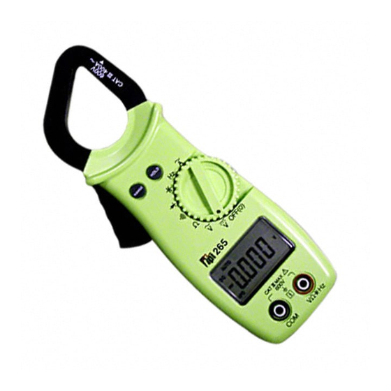
2. Product Description The 265 is a hand-held, autoranging clamp-on DMM. Extra large numerals, capacitance, frequency and data hold are just a few of the features of the 265. An affordable choice, the 265 offers measurements in all basic electrical functions. -
Page 4: Declaration Of Conformity
3. EC Declaration of Conformity This is to certify that TPI Model 265 conforms to the protection requirements of the council directive 89/336/EEC, in the approximation of laws of the member states relating to Electromagnetic compatibility and 73/23/EEC. The Low Voltage Directive by application of... -
Page 5: Safety Considerations
GENERAL GUIDELINES ALWAYS • Test the 265 before using it to make sure it is operating properly. • Inspect the test leads before using to make sure there are no breaks or shorts. -
Page 6: Technical Data
Meets CE and IEC 1010. Auto Off Automatically powers off after 10 minutes of inactivity. When active, APO is displayed on the LCD. NOTE: To disable Auto Off, hold down the RANGE button while turning on the 265. 561.8187 information@itm www. .com... -
Page 7: Product Applications
2. Product Applications Perform the following tests and/or measurements with the 265 and the appropriate function: HVAC/R DCmV • Thermocouples in furnaces. • Heat anticipator current in thermostats. • Line voltage. ACV or DCV • Control circuit voltage. OHMS • Compressor winding resistance. -
Page 8: Specifications
3. Specifications IEC 1010 Over Voltage: CAT II - 1000V CAT III - 600V Pollution Degree 2 UL 3111 Pending Temperature for gauranteed accuracy: 23ºC +5ºC DC VOLTS Range Res. Accuracy 400mV 0.1mV +/-(0.3% of reading + 5 digits) Impedance: 0.001V 10MΩ... -
Page 9: Diode Test
Ω) OHM ( Resistance, Range Res. Accuracy 400Ω 0.1Ω 4kΩ 0.001kΩ ±(0.8% of reading +5 digits) Overload Protection: 40kΩ 0.01kΩ 250VDC or AC RMS 400kΩ 0.1kΩ 4MΩ 0.001MΩ ±(2% of reading +10 digits) 40MΩ 0.01MΩ Frequency (Hz) Range Res. Accuracy 4000Hz 40.00kHz 0.01kHz... - Page 10 Capacitance Range Res. Accuracy 0.001nF 40nF 0.01nF 400nF 0.1nF Overload Protection: 4µF 0.001µF ±(3% of reading +10 digits) 500VDC or AC RMS 40µF 0.01µF 400µF 0.1uF 0.001mF ±(7% of reading +10 digits) nF= nanofarad, µF= microfarad, mF= millifarad General Max Voltage between any 600V input and ground Fuse Protection (µ...
-
Page 11: Measurement Techniques
D. MEASUREMENT TECHNIQUES 1. Controls and Functions: Jaws for Measuring AC Amps Only RANGE Push Button HOLD Push Button Trigger for Opening the Jaws Rotary Switch LCD Display with Function Annunciators Input Jacks 561.8187 information@itm www. .com... - Page 12 RANGE Activates manual ranging. Press and hold for 2 seconds to return to auto ranging. Rotary Switch Turns the 265 completely off. Used to measure DC volts. Used to measure AC volts. Ω Ω Used to measure resistance.
- Page 13 Controls and Functions: (cont.) Input Jacks Black test lead connection for all measurements except AC Amps. V/ Ω Ω / /Hz Red test lead connection for all measurements except AC Amps. 561.8187 information@itm www. .com...
-
Page 14: Step By Step Procedures
4. Set rotary switch to the V range. 5. Connect test leads to circuit to be measured. 6. Reconnect power to circuit to be measured. 7. Read the voltage on the 265. Optional Modes • HOLD: Freezes the reading on the LCD. -
Page 15: Measurement Procedure
4. Set rotary switch to the V range. 5. Connect test leads to circuit to be measured. 6. Reconnect power to circuit to be measured. 7. Read the voltage on the 265. Optional Modes • HOLD: Freezes the reading on the LCD. - Page 16 3. Plug red test lead into V/ input jack. Ω 4. Set the rotary switch to the function. 5. Connect test leads to circuit to be measured. 6. Read the resistance value on the 265. Optional Modes • HOLD: Freezes the reading on the LCD. •...
- Page 17 Measuring AC Amperage CAUTION! Do not attempt to make a current measurement with the test leads. The 265 measures the current by clamping the jaw around one conductor (wire). Clamping around more than one wire will result in erroneous readings. Make sure the temperature probe is NOT plugged in during this test.
- Page 18 3. Plug red test lead into V/ input jack. 4. Set the rotary switch to the position. 5. Connect test leads to circuit to be measured. 6. The 265 will beep and the LED will illuminate at Ω resistances of 35 or lower.
- Page 19 Measuring Diodes WARNING! Do not attempt to make diode measurements with the circuit energized. For accurate tests, remove the diode completely from the circuit prior to measuring it. Make sure the tempera- ture probe is NOT plugged in during this test. Instrument set-up: FUNC.
- Page 20 Measuring Capacitance WARNING! All capacitance measurements are to be made on de-energized circuits with all capacitors discharged only. Failure to de-energize and discharge capacitors prior to measuring them could result in instrument damage and/or personal injury. Make sure the temper- ature probe is NOT plugged in during this test.
- Page 21 Measuring Frequency WARNING! Never attempt a frequency measurement with a voltage source greater than 500V. Determine the voltage of any unknown fre- quency source before connecting the instrument in frequency mode. Make sure the temperature probe is NOT plugged in during this test.
-
Page 22: Other Features
Auto Power Off (APO) Automatically powers off after 10 minutes of inactivity. When active, APO is displayed on the LCD. NOTE: To disable Auto Off, hold down the RANGE button while turning on the 265. 561.8187 information@itm www. .com... -
Page 23: F. Application Notes
F. Application Notes (AC Volts) Disconnect power from the terminal block, find the fuse or circuit breaker that con- trols the block and turn it off. Set up the meter following the steps under “Measurement Procedure” on page 15. Then proceed with the following: •Connect the red test lead to the hot side of the block and... -
Page 24: Application Notes
Application Notes (DC Volts) The 265 will accurately measure rectified DC Voltages like those encountered in furnaces and other appliances even though many of these devices do not have output filtering or other signal conditioning. When measuring DC Voltage of a bat-... - Page 25 Application Notes (Resistance) When measuring resistance of a motor, make sure the power is disconnected prior to testing. Set up meter following steps under “Measurement Procedure” on page 16, and proceed with the following: • Connect the red test lead to one power input line of the motor and the black test lead to the other power input line of the motor.
- Page 26 Application Notes (AC Amps) When measuring AC Amps of a motor there are two types of measurements that can be made, running current and in-rush or start-up current. Start-up current will usually be much higher than running current. Set up the meter following the steps under “Measurement Procedure”...
-
Page 27: Trouble Shooting Guide
G. Trouble Shooting Problem Probable Causes Does not power up • Dead or defective battery • Broken wire from battery snap to PCB All functions except • Very weak battery that will ohms read high not turn on the low battery indicator on the LCD AC Volts do not read •... -
Page 28: Maintenance
The battery is replaced as follows: a. Disconnect and remove all test leads from live circuits and from the 265. b. Loosen the screw from the back of the 265 battery cover. c. Remove the battery compartment cover. d. Remove old battery and replace with new battery. -
Page 29: Accessories
Accessories Standard Accessories Part Number 9 Volt Alkaline Battery A009A Test Lead Set A040 Soft Carrying Pouch A255 Optional Accessories Part Number Fused Test Lead Kit FTLK3 Deluxe Test Lead Set TLS2000RB Carbon Monoxide Adapter A771 Pressure Adapter A620 Temperature Adapter A301 Differential Temperature Adapter A312... - Page 30 Notes: 561.8187 information@itm www. .com...
- Page 31 Notes: 561.8187 information@itm www. .com...
- Page 32 265 SPECIFICATIONS (PARTIAL LIST) ±0.5% Basic DCV Accuracy Func. Range Res. 400mV 0.1mV 0.001V 0.01V 400V 0.1V 600V 400mV 0.1mV 0.001V 0.01V 400V 0.1V 750V 0.1A 400A 400Ω 0.1Ω 4kΩ 0.001kΩ 40kΩ 0.01kΩ 400kΩ 0.1kΩ 4MΩ 0.001MΩ 40MΩ 0.01MΩ Capacitance 0.001nF...
Need help?
Do you have a question about the 265 and is the answer not in the manual?
Questions and answers