Table of Contents
Advertisement
Quick Links
Advertisement
Table of Contents

Related Manuals for TPI 709


Summary of Contents for TPI 709
- Page 1 Combustion Efficiency Analyzer Rev. 6.x Analyzers The Value Leader...
-
Page 2: Table Of Contents
Contents Introduction..........General Overview..........1, 2 Instrument Overview........... 3 ~ 7 Front View..........3 Keypad..........4 Back View..........5 Side Views..........6 Top View..........7 Basic Analyzer Functions........8, 9 Analyzer Batteries........8 Turning The Analyzer On & Fuel Selection.. 8, 9 Turning The Analyzer Off...... -
Page 3: Introduction
This warranty does not cover sensors damaged through misuse of the analyzer. You should keep the batteries of your 709 fresh so power is constantly being supplied to your sensors. The following guidelines will help prevent damage to your sensors: Always use the mini pump filter when testing flue gases. - Page 4 Always keep the A794 water trap / filter assembly clean and replace the filter as necessary. Replacement filter part number is A794F. This manual will guide you through the functions of the TPI 709 which will give you many years of reliable service.
-
Page 5: Instrument Overview
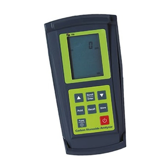
Instrument Overview Front View Rubber Boot Display Battery Condition Icon Selected Fuel Type Keypad Rubber Boot Protects the instrument from accidental damage Display Large 3 Parameter Backlit LCD Display Battery Condition Icon Shows condition of batteries. Keypad Selects all available functions Selected Fuel Type N GAS, LPG, LIGHT OIL, HEAVY OIL, OPT 1 (Bituminous Coal), OPT 2 (Anthracite Coal),... -
Page 6: Keypad
Keypad Scrolls through selectable fuels (see page 8 ) Switches between Gross and Newt Efficiency (see page 17) Switches between ºC and ºF (see pages 18 & 21) Moves up through the Stored Data Addresses Zeroes pressure reading (See page 21) Moves down through the Stored Data Addresses Scrolls through Combustion Analysis Displays (See 17&... -
Page 7: Back View
Back View Connections for Connection for Pressure Tubing Mini Pump Protection Filter Sample and Calibration and Pressure Inlet Information Ports Label Rubber Boot Battery Compartment Sample and Pressure Inlet Ports: Connection for Flue Probe (see pages 7 & 11) Connection for Mini Pump Protection Filter (see pages 7 &... -
Page 8: Side Views
Side Views Exhaust Port Infrared Window Rubber Boot Exhaust Port Port for connection of Exhaust Adapter Infrared Window Window for sending stored data to IR Printer (see page 25 ) Rubber Boot Protects the instrument from accidental damage... -
Page 9: Top View
Top View P (+) P (-) Gas Sampling Port T1 Socket Connection for thermocouple plug on flue probe (see page 11) Connection for any 'K' type thermocouple probe (see page 20) T2 Socket Connection for ambient 'K' type thermocouple probe (see page 11 ) Connection for any 'K' type thermocouple probe (see page 20) -
Page 10: Basic Analyzer Functions
The instrument MUST be turned on in a clean air environment as the initial purge will set the Carbon Monoxide level to Zero and the Oxygen to 20.9%. Press and hold down the Power Key and the TPI 709 will start its 30 second countdown 'PURGE' will be displayed. -
Page 11: Turning The Analyzer Off
Temperature, Pressure or Leak Detection readings and the default combus- tion display will be displayed. The 709 will auto power off if no keys have been pressed for 10 minutes and the CO level is below 15ppm. Auto off can be disabled (see Appendix D). The auto power off feature is always enabled upon power up. -
Page 12: Combustion Analysis Overview
To ensure accurate and consistent combustion tests, it is important gas and temperature samples be taken at the same location. This is easy with the TPI flue probe because the temperature sensor is an integral part of the probe. -
Page 13: Combustion Analyzer Mode
Please refer to Appendix A for general maintenance schedule and function tests. 1. Turn the 709 on in fresh air as outlined on page 8. After the initial purge cycle the 709 will default to combustion analyzer mode and combustion dis- play 1 will be seen. - Page 14 IMPORTANT: Prior to taking a sample, the device under test should be on and at operating temperature. Putting the flue probe in the sample area prior to starting the device may cause saturation of the sensors due to the higher initial concentration of carbon monoxide that may be encountered upon start up.
-
Page 15: Typical Test Locations
TYPICAL TEST LOCATIONS Atmospheric Gas Fired Fan Assist Boiler / Furnace Typical Test Locations Figure 1 It is important to use manufacturers recommended test locations whenever possible. - Page 16 TYPICAL TEST LOCATIONS Condensing Boiler / Furnace Typical Test Locations Figure 2 It is important to use manufacturers recommended test locations whenever possible.
- Page 17 TYPICAL TEST LOCATIONS Atmospheric Forced Air Furnace Typical Test Locations Test all exhaust ports at the top of the heat exchanger. Figure 3 It is important to use manufacturers recommended test locations whenever possible.
- Page 18 4. Insert the flue probe into the sample hole of the device under test. The probe tip should be in the middle of the flue pipe or exhaust stream. Ensure the In-Line Filter / Water Trap hangs below the analyzer in the proper vertical position when readings are being taken.
-
Page 19: Combustion Analysis Displays
5. Allow the readings to stabilize. Multiple combustion analysis displays are available to provide the various test results. Use the Scroll/Enter Key to move through the various combustion displays. • Combustion Display 1 (Default Start Up Display) • Displays Carbon Monoxide (CO) reading in parts per million (ppm) •... - Page 20 • Combustion Display 4 • Displays CO air free (-CF-) CO air free takes into account excess air (make up air) and factors this out of the displayed reading. Some systems inject extra air to ensure complete combustion. This can dilute the CO sample resulting in a low CO reading when the standard CO display is being read.
-
Page 21: Typical Test Results
Typical Test Results Actual test results vary depending on the equipment under test. TPI recommends you check with the manufacturer of the equipment being tested to determine specific acceptable results. Power Burners (Gas Fired) Oxygen 3% to 6% Carbon Monoxide Less than 100ppm (air free) -
Page 22: Thermometer Mode
Thermometer Mode With the analyzer running, press the Func Key to access the thermometer function. In this mode the 709 functions like a K-Type thermocouple ther- mometer. The pump will stop running when in this function. The thermometer func- Function Display 1 (Temperature) -
Page 23: Manometer Mode
The 709 incorporates a differential manometer. This means when a single hose is connected to the (+) port and pressure is applied, the 709 will read positive pressure. If a single hose is connected to the (-) port and pressure is applied, the 709 will read a negative pressure. -
Page 24: Setting Date & Time
SETTING DATE AND TIME With the analyzer running, press the Func Key repeatedly to access the date/time screen. From this function Time, Date and Year can be changed. Function Display 4 (Date / Time) Time Date / Month Year If the Date and Time do not need to be changed, press the Func Key to bypass this function and return the 712 to combustion analyzer mode (Function 1). -
Page 25: Storing Data
STORING DATA During testing data can be stored for later retrieval. When data is saved, all data previously in the address will be overwrit- ten.When saving pressure/draft readings, select an address different from the one used to save combustion readings. 1. -
Page 26: Recalling Data
3. Using the up and down arrows, select the memory location of the readings you want to display. 4. Press the Scroll/Enter key once. The 709 will display the date and time screen showing when that reading was stored. 5. Use the up and down arrows to scroll through the data that was saved. -
Page 27: Printing Data
‘rEAL’ will be flashing. To cancel printing press the Print Key and use the Up/Down Arrow Keys to select “Yes” and press the Scroll/Enter Key. Selecting ‘rEAL’ will cause the 709 to print the test data currently on the display (real time data). Selecting ‘Stor’ will cause the 709 to print data stored in memory. -
Page 28: Printing Data
PRINTING DATA (Continued) Printout Interpretation Date and time of combustion test. Fuel type selected during test. Data from combustion test is printed here. Smoke Test Result. For use on oil fired equipment. (Circle one to indicate the result of a smoke test performed using the optional A788 smoke test pump.) -
Page 29: Specifications
SPECIFICATIONS Instrument Operating Temperature Range 14°F to +122°F (-10°C to +50°C) Battery 1.5V AA size (3) Battery Life > 6 Hours Fuels Natural Gas, LPG, Light Oil, Heavy Oil OPT 1 (Bituminous Coal), OPT 2 (Anthracite Coal), OPT 3 (Coke), OPT 4 (Butane), OPT 5 (Wood), OPT 6 (Bagasse) Display... -
Page 30: Specifications
SPECIFICATIONS (Continued) Pressure Measurement Selectable Ranges mbar, kPa and inH2O Range - 150 mbar to + 150 mbar -15 kPa to + 15 kPa -60 inH O to 60 inH Resolution 0.01 mbar, 0.001 kPa, 0.001 inH Accuracy +/- 0.5% fsd Temperature Measurement Input Type K-Type thermocouple... -
Page 31: Calibration & Service
**Sensor replacement requires calibration gas. WARRANTY Your TPI 709 Flue Gas Analyzer is guaranteed free from defects in materials and workmanship for 3 Years from the date of purchase. This guarantee does not affect your statuary rights. For additional information please refer to the included warranty card or contact TPI at 800-368-5719. -
Page 32: Appendix A General Maintenance & Function Tests
TPI analyzers use three filters to protect the pump and sensors. The first filter to check is the A763 mini pump protection filter. (see picture below) - Page 33 Appendix A: General Maintenance (continued) Filter Check Continued The other two filters are located in the water trap. The main filter is the A794F particle filter. This filter stops debris and dust from traveling down to the analyz- er. The secondary filter is the A794W water block filter. This filter stops flow in the event the water trap fills with condensate.
- Page 34 Appendix A: General Maintenance (continued) Flue Probe Integrity Check NOTE: Perform this check after performing the Pump Operation Check outlined on the previous page. 1. Turn the analyzer on as outlined on page 8. Do not connect anything to the inlet.
-
Page 35: Appendix B A773 Sulfur Filter Installation & Maintenance
Appendix B: A773 SULFUR FILTER INSTALLATION & MAINTENANCE When performing combustion tests on oil fired equipment it is important to use the optional A773 sulfur filter. Failure to do so can result in incorrect and readings. This filter also protects the sensors from the affects of sulfur. The A773 does not have to be removed when working with other types of fuels. - Page 36 Appendix B: A773 SULFUR FILTER INSTALLATION & MAINTENANCE 4. Beginning on the “Flue Probe” side of the A773 sulfur filter, pull the yellow thermocouple cord out of the channel of the flue probe tube. Pull out approx- imately the length of the water trap that was removed. 5.
-
Page 37: Appendix C Error Codes And Troubleshooting
Appendix C: ERROR CODES & TROUBLESHOOTING The 709 analyzer will display certain codes to let you know of a malfunction. Code Code Definition Possible Causes Corrective Action Displayed The analyzer will perform Annual calibration is due. Last calibration was per- properly after this message formed over one year ago. - Page 38 Appendix C: ERROR CODES & TROUBLESHOOTING (Continued) Problem Possible Cause Corrective Action Efficiency reading incorrect NET efficiency selected. Select GROSS efficiency. See page 17. Ambient temperature probe Plug ambient probe into T2. not plugged in to T2. See page 11. Incorrect fuel selected.
-
Page 39: Appendix Dco Alarm & Auto Power Off
6. 709 Display: ‘20.9%’, ‘o2’, ‘rEF’. Action : Press the Func Key to bypass. 7. 709 Display: ‘2000’, ‘A-r’, ‘SEt’. Action : If you are not changing the CO alarm point press the Func Key. Otherwise press the Up and Down Keys to set the ppm level the alarm will sound at. -
Page 40: Appendix E Manually Initializing Sensors
13. 709 Display: ‘Auto’, ‘oFF’, ‘En’. Action : Press the Func Key to bypass. 14. 709 Display: ‘CAL’, ‘StoP’, ‘go’. Action : Press the Up Arrow Key to select ‘StoP’ by making it blink and press the Scroll/Enter Key to accept the selec- tion. -
Page 41: Appendix F Resetting Pressure Sensor Zero
10. 709 Display: ‘Auto’, ‘oFF’, ‘En’. Action : Press the Func Key to bypass. 11. 709 Display: ‘CAL’, ‘StoP’, ‘go’. Action : Press the Up Arrow Key to select ‘StoP’ by making it blink and press the Scroll/Enter Key to accept the selec- tion. -
Page 42: Appendix G Technical Notes
Appendix G: Technical Notes Note 1: When performing a pressure or draft test during a combustion test, the pump can be turned on to provide a continuous sample to the sensors. This enables pressure adjustments to be made and the affect to the combustion process can be seen by returning to combustion analyzer mode. -
Page 43: Appendix H Testing For Carbon Monoxide In Ambient Air
Appendix H: Testing for Carbon Monoxide in Ambient Air The 712 can be used to test for carbon monoxide in ambient air. For example tests can be performed in work spaces and living areas like offices and houses to ensure safety. 1. -
Page 44: Appendix I Carbon Monoxide Limits In Ambient Air Chart
Appendix I: Carbon Monoxide in Ambient Air Chart This chart contains maximum exposure levels and times for carbon monoxide. This is a general guidline only. It is recommended you check with your local government for guidelines in your area. -
Page 45: Appendix J Carbon Monoxide Facts
Appendix J: CARBON MONOXIDE FACTS Carbon Monoxide (CO) is invisible, odorless, and tasteless. It is the byproduct of combustion and levels are elevated when there is incomplete combustion. Sources of CO include: Unvented kerosene and gas space heaters Leaking chimneys & furnaces Gas water heaters Back drafting from furnaces Wood stoves&... -
Page 46: Appendix K Battery Replacement
Appendix K: Battery Replacement When the battery status indicator is empty the batteries should be changed immediately. For optimum performance replace the batteries with 3 AA size alkaline batteries. The procedure for replacing batteries is as follows: 1. Turn the analyzer over and locate the phillips head battery cover screw. See picture below.
Need help?
Do you have a question about the 709 and is the answer not in the manual?
Questions and answers