
Related Manuals for Arduino TC4+


Summary of Contents for Arduino TC4+
- Page 1 TC4+ Arduino Shield Quick Start Guide April 20, 2019 Contents 1 Overview 2 Assembly (kit version) 3 Connecting to your roaster 4 Software...
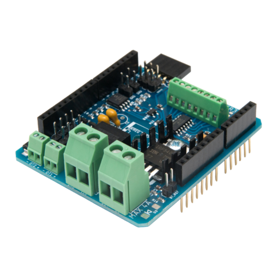
- Page 2 Figure 1: The TC4+ board and its on-board components. Overview The TC4+ is an Arduino shield providing a 4-channel thermocouple interface and driver logic for AC and DC loads. The main components on the board are shown above in Figure 1. The next page shows all connectors and status LEDs schematically.
- Page 3 Figure 2: Layout of TC4+ through-hole components. Assembly (kit version) If you purchased a TC4+ KIT, it will come with all surface-mount devices sol- dered, and loose through-hole components which you will have to solder yourself. Figure 2 shows the location of these components in different colours: Dark Red: Stackable headers.
- Page 4 Thermocouple header Bluetooth header Power LED TC4+ BT HDR CH2- CH2+ CH1- CH1+ CH4- CH4+ CH3- CH3+ BT SEL BT SEL jumper (set to BT Serial) IO2 & IO3 headers POWERLED OT1LED OT1 & OT2 OT2LED status LEDs I2C headers INPUT - OT2 + - OT1 +...
- Page 5 LEDs on the TC4+. See the end of the section for a complete application example. Connecting to the Arduino Stack the TC4+ shield on top of an Arduino Uno R3, or compatible. The long pins on the underside of the TC4+ go into the corresponding headers on the top side of the Arduino.
- Page 6 Figure 5: A flyback diode across the motor. motor, connecting a DC power supply is required. If not, this is optional - the TC4+ and Arduino could alternatively be powered by USB. The DC power supply should match the voltage of the DC motor. That is, if your motor needs 20V, choose a 20V PSU.
- Page 7 This allows wireless roast monitoring and control. With a HC-05 (but not HC- 06), you can also wirelessly upload Arduino sketches. See Figure 6 for how to connect either module. See the configuration section for details on how to set...
-
Page 8: Application Example
Further to the connectors discussed, the TC4+ features the headers, jumpers and status LEDs listed below. IO2, IO3 break out the Arduino’s IO2 and IO3 ports and GND. Note that IO3 is also connected to the MOSFET. I2C provides two 4-pin I2C headers for displays etc. - Page 9 Roast Chamber TC2 (bean temp) TC1 (air temp) heater HC-05 thermal fuse TC4+ flyback diode CH2- CH2+ CH1- CH1+ CH4- CH4+ CH3- CH3+ - OT2 + - OT1 + +8-28V DC PSU Figure 7: A typical application example of the TC4+ board. This shows the TC4+ board connected to a DC PSU;...
- Page 10 Software Arduino sketch The most commonly used Arduino sketch is aArtisanQ PID, available at https: //github.com/greencardigan/TC4-shield/tree/master/applications/Artisan/ aArtisan_PID/trunk/src/aArtisanQ_PID For all the configurations discussed in this guide, you will want to use this in PWM configuration mode. Artisan You will usually want to use Artisan on your host computer, available at https: //artisan-scope.org/.
Need help?
Do you have a question about the TC4+ and is the answer not in the manual?
Questions and answers