Advertisement
Description
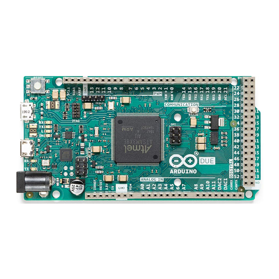
The Arduino Due is a groundbreaking microcontroller board featuring the Atmel SAM3X8E ARM Cortex-M3 CPU, making it the first Arduino board built around a 32-bit ARM core microcontroller. With its 54x digital input/output pins, 12x analog inputs, 4x UARTs, USB OTG capability, and 84 MHz clock, the Due offers enhanced performance and versatility for a wide range of projects. Compatible with all Arduino shields designed for operation at 3.3 V and compliant with the 1.0 Arduino pinout standard, the Due is a powerful tool for both beginners and experienced makers alike.
Target Areas
Embedded Systems Development, Robotics, 3D Printing, CNC Machines, Prototyping
Application Examples
The Arduino Due combines the performance of the Atmel SAM3X8E microcontroller with the flexibility of the Arduino platform, offering a versatile solution for developers, hobbyists, and professionals alike. With its 32-bit architecture and clock speed of 84 MHz, the Due delivers robust performance for demanding applications.
- Embedded Systems Development: The Arduino Due can be utilized to create a real-time data acquisition system for monitoring and analyzing environmental parameters in industrial settings. By interfacing sensors such as temperature, humidity, and pressure sensors with the Due's abundant I/O pins, developers can capture real-time data and process it using the Due's powerful microcontroller. The system can then transmit this data wirelessly or via USB to a host computer for analysis, allowing for continuous monitoring and remote management of critical processes.
- Robotics: The Arduino Due can serve as the brain of an autonomous mobile robot capable of navigating and interacting with its environment. By integrating sensors such as ultrasonic range finders, gyroscopes, and encoders, developers can equip the robot with perception capabilities to sense its surroundings and detect obstacles. Using the Due's abundant I/O pins and powerful processing capabilities, algorithms for localization, mapping, and path planning can be implemented to enable autonomous navigation. Additionally, actuators such as motors or servos can be controlled by the Due to execute motion commands, allowing the robot to move and manipulate objects in its environment autonomously.
- 3D Printing & CNC Machines: The Arduino Due can function as a versatile controller for DIY projects. By interfacing stepper motor drivers and end-stop switches with the Due's numerous I/O pins, enthusiasts can create their own 3D printers or CNC machines. The Due's high-speed processing capabilities enable precise control of stepper motors for accurate positioning and movement.
- Prototyping: The Arduino Due serves as an invaluable tool for quickly iterating and testing new ideas for IoT devices. By leveraging the Due's extensive I/O capabilities and compatibility with various sensors, communication modules, and actuators, developers can rapidly assemble and test prototypes of IoT devices. Whether it is a smart home sensor node, a weather station, or a remote monitoring system, the Arduino Due provides a flexible platform for integrating components, writing firmware, and validating functionality. With the Due's support for Arduino libraries and easy-to-use development environment, prototypers can focus on innovation and experimentation, accelerating the process of bringing ideas to fruition.
Features
General Specifications Overview
The Arduino Due is a versatile microcontroller board designed for a wide range of applications. Powered by the Atmel SAM3X8E ARM Cortex-M3 CPU, it offers high performance and a robust set of features, making it suitable for complex projects. The Due's 32-bit architecture provides enhanced processing capabilities compared to traditional Arduino boards. Designed with a similar form factor to the Arduino® Mega, it maintains compatibility with most Arduino shields through its extensive set of I/O pins and headers. The following table summarizes the board's main features.
| Feature | Description |
| Microcontroller | Atmel SAM3X8E ARM Cortex-M3 32-bit ARM Cortex-M3 / 84 MHz Clock speed |
| Memory | SAM3X 512 KB Flash / 96 KB SRAM (divided into two banks: 64 KB and 32 KB) |
| USB-to-serial | ATmega16U2 connected to the SAM3X hardware UART |
| Digital Inputs | Digital Inputs not 5 V compatible (x54) |
| Analog Inputs | The Due's analog inputs pins measure from ground to a maximum value of 3.3 V (x12) |
| PWM Pins | PWM Pins with 8 bits resolution (x12) |
| Communication | UART (x4), I2C (x2), SPI (x1 SPI header), Native USB port (x1), Programming USB port (x1) |
| Power | Input voltage (VIN): 7-12 VDC / DC Current per I/O Pin: 8 mA |
| Dimensions | 101.6 mm x 53.34 mm |
| Weight | 36 g |
| Operating Temperature | -40°C to +85°C |
| Certifications | CE/RED, UKCA, FCC, IC, RCM, RoHS, REACH, WEEE |
Microcontroller
| Component | Details |
| Atmel SAM3X8E | 32-bit ARM Cortex-M3 at 84 MHz |
| Flash Memory | 512 KB |
| Programming Memory | 96 KB SRAM (divided into two banks: 64 KB and 32 KB) |
Inputs
| Characteristics | Details |
| Number of inputs | 54x digital inputs, 12x analog inputs |
| Inputs overvoltage protection | Yes |
| Antipolarity protection | Yes |
Outputs
| Characteristics | Details |
| DAC1 and DAC2 | True analog output 12-bits resolution (4096 levels) |
| PWM outputs | 12x PWM outputs |
Accessories
- USB Cable Type-A Male to Micro Type-B Male (Not included)
Related Products
- Arduino Mega Proto Shield Rev3 (A000080)
- Arduino 4 Relays Shield (A000110)
- Arduino Motor Shield Rev3 (A000079)
Rating
Recommended Operating Conditions
| Symbol | Description | Min | Typ | Max | Unit |
| VIN | Input voltage from VIN pad | 6.0 | 7.0 | 16 | V |
| VUSB | Input voltage from USB connector | 4.8 | 5.0 | 5.5 | V |
| VDD | Input high-level voltage | 0.7*VDD | VDD | V | |
| VIL | Input low-level voltage | 0 | 0.3*VDD | V | |
| TOP | Operating Temperature | -40 | 25 | 85 | °C |
 Note: VDD controls the logic level and is connected to the 3.3 V power rail. VAREF is for the analog logic.
Power Specification
| Property | Min | Typ | Max | Unit |
| Supply voltage | 7.0 | - | 12 | V |
| Permissible range | 6.0 | - | 16 | V |
Safety Note: Unlike most traditional Arduino boards, the Arduino Due board runs at 3.3 V. Keep in mind the maximum voltage that the I/O pins can tolerate is 3.3 V. Applying voltages higher than 3.3 V to any I/O pin could damage the board.
Current Consumption
| Parameter | Symbol | Min | Typ | Max | Unit |
| Normal Mode Current Consumption | INM | 130 | --- | 800 | mA |
Functional Overview
Pinout
The Arduino Due pinout is shown in the following figure.

Arduino Due pinout
Safety Note: Disconnect power before board modifications to avoid short-circuiting.
Full Pinout Table
The full pinout of the Arduino Due is available in the following tables.
Board's 24-Pin Header

Board's 24-Pin Header pinout
Board's 26-Pin Header

Board's 26-Pin Header pinout
SPI
The board provides an SPI interface and full access to its pinout as it can be seen in the following table.
SPI pinout:
| Pin | Function | Type | Description |
| 1 | CIPO | Internal | Controller In Peripheral Out |
| 2 | +5V | Internal | Power Supply of 5V |
| 3 | SCK | Internal | Serial Clock |
| 4 | COPI | Internal | Controller Out Peripheral In |
| 5 | RESET | Internal | Reset |
| 6 | GND | Internal | Ground |
Digital Pins D22 - D53 LHS

D22 - D53 LHS pinout
Digital Pins D22 - D53 RHS

D22 - D53 RHS pinout
JTAG Pins
The board provides access to the debugging interface using the JTAG pins as it can be seen in the following table.
Debugging's JTAG pinout:
| Pin | Function | Type | Description |
| 1 | Reset | Reset | Reset |
| 2 | GND | Power | GROUND |
| 3 | TDI | Digital | Test Data In |
| 4 | N/C | - | Not Connected |
| 5 | TDO | Digital | Test Data Out |
| 6 | GND | Power | GROUND |
| 7 | TCK | Digital | Test Clock |
| 8 | GND | Power | GROUND |
| 9 | TMS | Digital | Test Mode Select |
| 10 | +3V3 | Power | +3V3 Power Rail |
Block Diagram
The block diagram with the main parts of the product can be checked in the following image:

Arduino Due Block Diagram
Power Supply
The Arduino Due can be powered in multiple ways:
- USB Type-B port (Native port and Programming port).
- Using an external voltage source connected to VIN pin, which has a recommended voltage range of 7-12 VCC.
- The Power Jack: The Due can be powered using a DC power supply connected to the power jack, which accepts a voltage range of 7 to 12 V.
It is essential to note that the Arduino Due operates at 3.3 V, so any external power source must be regulated to this voltage level. Additionally, the power supply should be able to provide sufficient current for the board's operation and any connected peripherals.

Arduino Due Power Tree
Product Topology
In the following drawing you can see the main integrated circuits and passive components of the Arduino Due board.

Arduino Due Topology
| Ref. | Description |
| U1 | Atmel SAM3X8E ARM Cortex-M3 |
| USB1 | Native USB port |
| USB2 | Programming USB port |
| X2 | Power Jack VIN 7-12 VCC |
| ERASE | ERASE Button |
| RESET | Reset Button |
| DEBUG | Debug JTAG pinnout |
| SPI | SPI pinout |
| ICSP1 | ICSPI1 Pinout |
JTAG Connector
Debugging capabilities are integrated directly into the Arduino Due and are accessible via the 6-pin JTAG connector.
JTAG pinout:
| Pin | Function | Type | Description |
| 1 | Reset | Reset | Reset |
| 2 | GND | Power | GROUND |
| 3 | TDI | Digital | Test Data In |
| 4 | N/C | - | Not Connected |
| 5 | TDO | Digital | Test Data Out |
| 6 | GND | Power | GROUND |
| 7 | TCK | Digital | Test Clock |
| 8 | GND | Power | GROUND |
| 9 | TMS | Digital | Test Mode Select |
| 10 | +3V3 | Power | +3V3 Power Rail |
Native USB Port
The Arduino Due's Native USB port features a USB Type-B connector. This port allows the board to communicate directly with a computer as a USB device, enabling functionalities such as USB host/device capabilities and USB OTG (On-The-Go) functionality.

Arduino Due USB port
Programming USB Port
This port allows the board to be programmed and powered via a USB connection to a computer. It facilitates serial communication between the Arduino Due and the computer, enabling the uploading of sketches and interaction with the Arduino IDE. The port is connected to the ATmega16U2 microcontroller, which acts as a USB-to-serial converter, simplifying the programming process. When connected to a computer, the Arduino IDE recognizes the board as a COM port, enabling seamless communication for programming and debugging purposes.
Board's 24-Pin Header Connector
The 24-pin header connector provides a range of interfaces and general-purpose pins essential for various applications
These pins offer a range of functionalities, including analog and digital input/output, power supply connections, analog-to-digital, digital-to-analog conversion and CAN bus communication.

Board's 24-Pin Header pinout
Board's 26-Pin Header Connector
The 26-pin header connector on the Arduino Due offers a comprehensive set of interfaces and versatile pins crucial for diverse applications
These pins offer a range of functionalities, including digital input/output, serial communication, PWM (Pulse Width Modulation) outputs, and I2C (Inter-Integrated Circuit) communication.

Board's 26-Pin Header pinout
SPI
These pins facilitate communication between the Arduino Due and external SPI devices
SPI pinout:
| Pin | Function | Type | Description |
| 1 | CIPO | Internal | Controller In Peripheral Out |
| 2 | +5V | Internal | Power Supply of 5 V |
| 3 | SCK | Internal | Serial Clock |
| 4 | COPI | Internal | Controller Out Peripheral In |
| 5 | RESET | Internal | Reset |
| 6 | GND | Internal | Ground |
D22 to D53 on Left and Right Side
These digital pins provide a wide range of GPIO (General Purpose Input/Output) capabilities for interfacing with external sensors, actuators, and other digital devices in Arduino Due projects.
D22 - D53 LHS pinout:
| Pin | Function | Type | Description |
| 1 | +5V | Power | +5V Power Rail |
| 2 | D22 | Digital | GPIO 22 |
| 3 | D24 | Digital | GPIO 24 |
| 4 | D26 | Digital | GPIO 26 |
| 5 | D28 | Digital | GPIO 28 |
| 6 | D30 | Digital | GPIO 30 |
| 7 | D32 | Digital | GPIO 32 |
| 8 | D34 | Digital | GPIO 34 |
| 9 | D36 | Digital | GPIO 36 |
| 10 | D38 | Digital | GPIO 38 |
| 11 | D40 | Digital | GPIO 40 |
| 12 | D42 | Digital | GPIO 42 |
| 13 | D44 | Digital | GPIO 44 |
| 14 | D46 | Digital | GPIO 46 |
| 15 | D48 | Digital | GPIO 48 |
| 16 | D50 | Digital | GPIO 50 |
| 17 | D52 | Digital | GPIO 52 |
| 18 | GND | Power | Ground |
D22 - D53 RHS pinout:
| Pin | Function | Type | Description |
| 1 | +5V | Power | +5V Power Rail |
| 2 | D23 | Digital | GPIO 23 |
| 3 | D25 | Digital | GPIO 25 |
| 4 | D27 | Digital | GPIO 27 |
| 5 | D29 | Digital | GPIO 29 |
| 6 | D31 | Digital | GPIO 31 |
| 7 | D33 | Digital | GPIO 33 |
| 8 | D35 | Digital | GPIO 35 |
| 9 | D37 | Digital | GPIO 37 |
| 10 | D39 | Digital | GPIO 39 |
| 11 | D41 | Digital | GPIO 41 |
| 12 | D43 | Digital | GPIO 43 |
| 13 | D45 | Digital | GPIO 45 |
| 14 | D47 | Digital | GPIO 47 |
| 15 | D49 | Digital | GPIO 49 |
| 16 | D51 | Digital | GPIO 51 |
| 17 | D53 | Digital | GPIO 53 |
| 18 | GND | Power | Ground |
Device Operation
Getting Started - IDE
If you want to program your Arduino Due while offline you need to install the Arduino® Desktop IDE [1]. To connect the Arduino Due to your computer, you will need a USB Type-B cable, which can also provide power to the board, as indicated by the LED (DL1).
Getting Started - Arduino Web Editor
All Arduino boards, including this one, work out-of-the-box on the Arduino® Web Editor [2], by just installing a simple plugin.
The Arduino Web Editor is hosted online, therefore it will always be up-to-date with the latest features and support for all boards. Follow [3] to start coding on the browser and upload your sketches onto your board.
Getting Started - Arduino Cloud
All Arduino IoT enabled products are supported on Arduino Cloud which allows you to log, graph and analyze sensor data, trigger events, and automate your home or business.
Online Resources
Now that you have gone through the basics of what you can do with the board you can explore the endless possibilities it provides by checking exciting projects on ProjectHub [4], the Arduino Library Reference [5], and the online store [6]; where you will be able to complement your board with sensors, actuators and more.
Board Recovery
All Arduino boards have a built-in bootloader which allows flashing the board via USB. In case a sketch locks up the processor and the board is not reachable anymore via USB, it is possible to enter bootloader mode by double-tapping the reset button right after the power-up.
Mechanical Information
The Arduino Due is a microcontroller board measuring 101.52 mm x 53.3 mm, featuring two USB-B connectors and a big quantity of GPIO pins headers.
Board Dimensions
The Arduino Due board outline and mounting holes dimensions are shown in the figure below; all the dimensions are in mm.

Arduino Due Mounting Holes And Board Outline
Board Connectors
Connectors of the Arduino Due are placed on the left side of the board; their placement is shown in the figure below. All the dimensions are in mm.

Arduino Due Technical drawing
Documents / ResourcesDownload manual
Here you can download full pdf version of manual, it may contain additional safety instructions, warranty information, FCC rules, etc.
Advertisement


Need help?
Do you have a question about the Due and is the answer not in the manual?
Questions and answers