Table of Contents
Advertisement
Quick Links
Advertisement
Table of Contents

Related Manuals for Baumer PA403


Summary of Contents for Baumer PA403
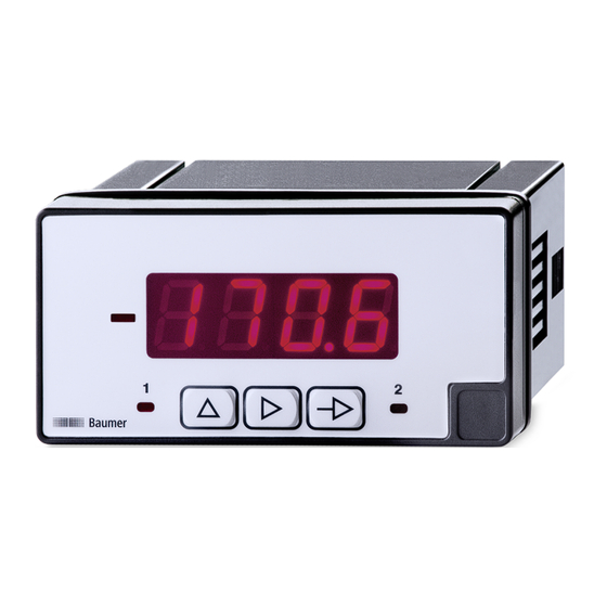
- Page 1 Operating Manual PA403 EN-US Prozess display...
-
Page 2: Table Of Contents
LED indicator............................11 6 Operating functions ............................ 13 Input signal configuration ........................13 Configuration of the display......................... 14 Configuration of the limit value outputs ....................17 Set limit values ............................ 19 Protect programming level via code....................20 Operating Manual PA403 | V1... - Page 3 List of illustrations List of illustrations Ill. 1 Block diagram of the configuration modules ..................12 Ill. 2 Limit value outputs - Time delay ......................17 Ill. 3 Limit value outputs - asymmetrical hysteresis..................17 V1 | PA403 Operating Manual...
-
Page 4: About This Document
The illustrations are examples only. Deviations are at the discretion of Baumer at all times. The manual is a supplementary document to the existing product documentation. -
Page 5: Warnings In This Manual
Indicates a danger with low risk, which could lead to light or medium injury if not avoided. NOTE Indicates a warning of material damage. INFO Indicates practical information and tips that enable optimal use of the devices. V1 | PA403 Operating Manual... -
Page 6: General Functionality
The process display is intend for visualizing, monitoring, control and calculation of measured values in industrial applications. Voltage input up to 600V AC/DC Current input up to 5A AC/DC Display range can be linearized LED display, 4-digit, programmable DIN housing 96 x 48 mm Operating Manual PA403 | V1... -
Page 7: Mounting The Process Display
Instruction: a) Prepare the cut-out according to the dimensions. b) Push device (1) with seal (2) into the cut-out. c) Secure the device from behind using the clamping frame (3). d) Perform the electrical connection. V1 | PA403 Operating Manual... -
Page 8: Electrical Connection Of The Process Display
Current max. 1 A Shunt max. 100 mV Voltage max. 20 V Voltage max. 200 V Voltage max. 600 V Relay output (3), optional Two relays normally closed 1 Inverter 1 normally open 1 normally closed 2 Inverter 2 normally open 2 Operating Manual PA403 | V1... -
Page 9: Connection Examples
Process display 1A AC MAX. Connection direct: Process display range -5...+5 A DC and 0...+5 A AC 5A DC/AC MAX. Connection via converter Process display 5A AC MAX. Input Shunt Connection: Process display Range -100...+100 A DC and 0...+100 mV AC 100mV DC/AC MAX. V1 | PA403 Operating Manual... - Page 10 Electrical connection of the process display Baumer Input voltage Connection: Process display Range -20...+20 V DC and 0...+20 V AC 20V DC/AC MAX. Connection: Process display Range -200...+200 V DC and 0...+200 V AC 200V DC/AC MAX. Connection: Process display Range -600...+600 V DC and 0...+600 V AC 600V DC/AC MAX. Operating Manual PA403 | V1...
-
Page 11: Interfaces
Call mode PROG Programming line selection Button MIN/MAX display Digit/Function selection Button – Incrementing the selected Button digit LED 1 Output 1 active LED plus/minus sign Enabled with negative dis- Enabled with negative input played values values V1 | PA403 Operating Manual... - Page 12 NOTICE Access to programming can be blocked at programming level. The various programming lines can then only be visualized but not changed. When entering the programming level, then appears instead of Operating Manual PA403 | V1...
-
Page 13: Operating Functions
DC voltage AC voltage Confirm with Select voltage Select the voltage range with button 600 V 200 V 20 V Confirm with Select current Select the currant range with button 5 A 1 A Shunt 100 mA Shunt 60 mA Confirm with V1 | PA403 Operating Manual... -
Page 14: Configuration Of The Display
(teach value 1 mode). Displayed value 2 Measured Measured value 1 value 2 Configuration Display INFO Only the configuration parameters for the selected input signal can be selected. Operating Manual PA403 | V1... - Page 15 Second measured value Keypad entries from -9999 to 9999. Display value for the second measured value The value entered here will be displayed upon the input signal reaching the second measured value. Ranging from -9999 to 9999 V1 | PA403 Operating Manual...
- Page 16 Defines the limit frequency of the low-pass filter (Fc) applied to smoothen unwanted display fluc- tuations. Programmable from 0 to 9 with the button Increasing the filter value reduces the response time of the display. The value 0 deactivates the filter. Confirm with Operating Manual PA403 | V1...
-
Page 17: Configuration Of The Limit Value Outputs
The hysteresis is programmed in display units from 0 to 9999. This only takes effect when the limit value outputs are switched off. Limit 1 Hysteresis Limit 2 Hysteresis Relay 1 = HIGH Relay 2 = Ill. 3: Limit value outputs - asymmetrical hysteresis Configuration of the Limit values V1 | PA403 Operating Manual... - Page 18 Function of the relay output Time delay Hysteresis Delay or hysteresis value Programming the delay (dLY) from 0 to 99 s or hysteresis (HYS) from 0 to 9999 display units. Configuration is in an analog way to [Set1]. Operating Manual PA403 | V1...
-
Page 19: Set Limit Values
It is possible to lock/unlock the keypad to prevent the setpoint from being changed. Press the button , the message [CodE] is displayed. Press the button for 5 seconds to call up the lock/unlock menu. V1 | PA403 Operating Manual... -
Page 20: Protect Programming Level Via Code
Yes, all configuration modules are protected against modification and de- vice exits the programming level. Change code Change the code here, the new code is saved into the device and you exit programming level. Operating Manual PA403 | V1... - Page 24 Baumer Germany GmbH & Co. KG Bodenseeallee 7 DE-78333 Stockach www.baumer.com...
Need help?
Do you have a question about the PA403 and is the answer not in the manual?
Questions and answers