Table of Contents
Advertisement
Quick Links
Operating instructions
Interface description
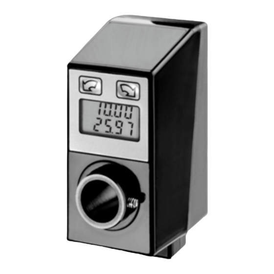
N 152 spindle position display (SPA)
Firmware 01
Version 1.10 and up
Contents
1.
1.1.
1.2.
2.
3.
3.1.
3.2.
3.3.
3.4.
3.5.
3.6.
3.7.
3.8.
4.
4.1.
4.2.
4.3.
4.4.
4.5.
5.
5.1.
5.2.
5.3.
6.
7.
7.1.
8.
Baumer IVO GmbH & Co. KG
Dauchinger Strasse 58-62
Phone +49 (0)7720 942-0
www.baumer.com
info.de@baumerivo.com
•
DE-78056 Villingen-Schwenningen
•
Fax +49 (0)7720 942-900
•
Page
2
2
3
3
5
5
6
6
6
6
7
7
7
8
8
8
15
23
25
27
27
27
27
28
29
30
30
02.10
171.02.315/4
•
Subject to modification
in technic and design.
Advertisement
Table of Contents

Subscribe to Our Youtube Channel
Related Manuals for Baumer N 152


Summary of Contents for Baumer N 152
-
Page 1: Table Of Contents
Operating instructions Interface description N 152 spindle position display (SPA) Firmware 01 Version 1.10 and up Contents Page General information 1.1. Safety precautions 1.2. SPA description and explanation Terminal assignment Interface 3.1. Interface data 3.2. Protocol 3.3. Checksum (Cyclic Redundancy Check) 3.4. -
Page 2: General Information
N 152 1. General information 1.1. Safety precautions General remarks The equipment is designed and assembled according to the prevailing regulations of technology. The equipment left the manufacturer in perfect working order and in line with all safety-relevant conditions. To maintain this... -
Page 3: Spa Description And Explanation
„actual value“ N 152 enables motor connection using the 12-core cable. Two softkeys on the keypad serve for manual motor trigger. Automated motor trigger by master is also possible. Motor supply is provided separately. - Page 4 N 152 Connecting motor to SPA N152 Motor connection to SPA is provided by 12-pin female connector. Assignment Significance Core colour Pin A n.c. Pin B IN 1 motor ccw yellow Pin C IN 2 motor cw blue Pin D...
-
Page 5: Interface
N 152 Circuit diagram Betriebs- 24 V OUT 1 spannung Linkslauf IN 1 (links) Rechtslauf IN 1 Ausgang IN 2 (rechts) Freigabe Linkslauf Drehzahl IN 1 Eingang IN 4 (speed) nicht belegt IN 2 Ausgang 24 V Freigabe nicht belegt... -
Page 6: Protocol
N 152 3.2. Protocol The spindle position display operates with ASCII protocol (clear text protocol). Depending on the command, the protocol data package varies between 5 and 17 bytes. Byte Hex code Significance Values SOH = start of heading permanent 01h Adr = identifier 00...31dez + 20h offset (identifier 00 = 20h) -
Page 7: Data Saving
N 152 3.6. Data saving Specific parameters are saved in EEPROM (1.000.000 writing cycles). Data saving is via interface upon every parameter transmission to SPA. Important: There should not be a cyclic transmission of these parameters to SPA but only if necessary, for example in case of parameter alteration. -
Page 8: Command Explanations
N 152 4. Command explanations 4.1. General information The following is describing the individual interface commands broken down into the four groups below: operating commands [ commands required during operation ] parameter commands [ commands for SPA parameterization ] identifier commands... - Page 9 N 152 Command extension Check Position „CX“ Command extension „Check Position CX “provides besides the alignment status target versus current value also the contents of the status and error register as well as the current value. The profile number is not transmitted.
- Page 10 N 152 Motor holding torque on / off „DB“ (44h, 42h) Prior to utilizing “DB” command to activate / deactivate the holding torque it must be enabled first in command „m“ since otherwise command „DB“ remains ineffective. Holding torque ever ON means that only motive shaft positioning operations are possible - either by aid of the two keys provided or by a corresponding command via interface.
- Page 11 (2Dh) together with 5 data bytes is replied. Positive values are represented by 6 data bytes without sign. Values inferior to 5(4) digits will come with preceding zeroes. Please note that N 152 provides a 5-digit actual value.
- Page 12 N 152 4.2.5. Read / write target profile „S“ (53h) This command is utilized to read the presently active target (profile value) respectively to read or write a specific target. Data are composed by profile number (2 bytes) and target (6 bytes). Note: Negative targets are transmitted as 5-digit number (see example 3).
- Page 13 N 152 Transmitting targets with simultaneous motor start signal Specific applications require autonomous re-alignment of shafts to the new target when it is received without prior enable signal by command „D“. For this intention the following commands are available: SPF transmits to SPA profile number together with motor start signal for automated positioning operations SDF transmits to SPA position value together with motor start signal for automated positioning operations The addressed SPA is enabled by adding sub-command „F“...
- Page 14 N 152 4.2.8. Set actual value as preset „Z“ (5Ah) Command “Z” is utilized to set the actual value at any optional value. The required position value is transmitted to SPA. The SPA will calculate a so-called “preset offset” value relating to the true absolute encoder position.
-
Page 15: Parameter Commands
N 152 4.2.9. Indicate optional column of figures in upper line „t“ (74h) This command is utilized to indicate a 5-digit number in the upper line of the display. The numerical column is indicated less dot respectively comma. Preceding zeroes as well as both arrows are suppressed. The bottom line still indicates the actual value. - Page 16 N 152 4.3.1. Read / write bit parameters „a“ (61h) To exploit maximum memory capacity, several parameters are put together and transferred as “data pack” under the following parameter codes: Data1: 1 0 X X 0 X 0 X ┬ ──┬── ─┬─ ─┬─...
- Page 17 N 152 Counting mode This parameter assigns either „ascending“ or „descending” counted values in relation to the shaft’s direction of rotation. Following parameters are available: 00 = Up Clockwise rotation, ascending counted values 01 = Down Clockwise rotation, descending counted values...
- Page 18 N 152 Resolution This parameter defines the resolution of the actual value. Upon altering the resolution the decimal point is shifted correspondingly by one digit to the right or left, same applies also to actual value and target. The target values however are not converted correspondingly but only the decimal point is shifted.
- Page 19 N 152 Significance of parameter „m“ Key assignment This parameter assigns a specified direction of rotation to a certain key. For the mounting option “keypad below display” and the remaining default parameters applies the following: 0 = Up left/right key actuation = shaft rotation ccw/cw, counting mode UP/DOWN...
- Page 20 N 152 Holding torque This parameter is utilized to enable respectively disable the motor holding torque. Both directional signals “motor ccw” and “motor cw” are activated by the spindle position display (SPA). Thus, the motor is hold at its actual position.
- Page 21 N 152 SOH Adr Cmd MIN limit position = 0015.00 MAX limit position = 0850.25 EOT CRC Response Example 2: Write limit positions (MIN = -33.22; MAX = 1234.56) SOH Adr Cmd MIN limit position = -033.22 MAX limit position = 1234.56...
- Page 22 N 152 4.3.8. Read / write timeout at bus error RS485 „j“ (6Ah) This command is utilized to read or write the system time: timeout at bus error. Value range is within 00,1 s to 99,9 s. Tolerance: ±7% at minimum time; < 1‰ at maximum time, approx. 1% at 1.
-
Page 23: Identifier (Address) Commands
N 152 Example 2: Write jog step SOH Adr Cmd SCmd Jog step = 50 EOT CRC Transmission SCmd SOH Adr Cmd Schrittweite = 50 EOT CRC Response Example 3: Value transmitted is too high (4 digits) SOH Adr Cmd... - Page 24 N 152 4.4.1. Assigning device identifiers in the network „A“ (41h) This command is creating an automated process assigning the device identifier in successive order to every single SPA upon commissioning of the system. The first identifier to be assigned is broadcasted to all networked...
-
Page 25: Specific Commands
N 152 4.5. Specific commands Command Data amount read write Broad- Saved in Significance code in bytes cast EEPROM K (4Bh) Specific command: profile reset (clear) Q (51h) Specific command: SPA reset X (58h) 2 / 4 / 8 Specific commands 4.5.1. - Page 26 Data = S (53h) = read serial number Example 1 : Read version number Data Transmission Data Version number = 2.00 Response Example 2: Read device type (device type = N 152; firmware = 01) Data Transmisison Data Type Response Code configuration of the transmitted device type:...
-
Page 27: Error Warnings
N 152 5. Error warnings 5.1. CRC error Upon recognizing a CRC error in a transmitted command the SPA will respond as follows: Error Response Error = „e“ (65h) = CRC error 5.2. Format error Upon recognizing a format error (incorrect length of protocol or void command (Cmd) in a command transmitted... -
Page 28: Overview On Commands
N 152 Target transmitted respectively DIM parameter is above the MAX limit. Note: Take loops into consideration. Troubleshooting: Transmit new admissible position value. Target transmitted respectively DIM parameter is below the MIN limit. Note: Take loops into consideration. Troubleshooting: Transmit new admissible position value. -
Page 29: Technical Data
Directional arrows Tolerance window Rounding function Motive positioning Two softkeys with jog operation for format alignment Direct motor connection of N 152 by motor cable Standard DIN EN 61010-1 Protection class II Overvoltage category II Pollution degree 2 Interference emission... -
Page 30: Dimensions
N 152 7.1. Dimensions Optional display Torque pin position 0.5x 45° Pin M4 Seal M16 male connector / motor 31.8 M8 mal e connector 8. Part number Reference Interface RS485 E-connection Connector output M8, motor cable 0.5 m Cable output M8, motor cable 1.5 m...
Need help?
Do you have a question about the N 152 and is the answer not in the manual?
Questions and answers