Table of Contents
Advertisement
Quick Links
Advertisement
Table of Contents

Related Manuals for Baumer PA418


Summary of Contents for Baumer PA418
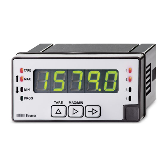
- Page 1 Operating Manual PA418 EN-US Process display...
-
Page 2: Table Of Contents
Configuration of the display......................... 16 Configuration of the limit value outputs ....................20 Configuration of the analog output ...................... 23 Control input configuration ........................24 Set limit values ............................ 26 Protect programming level via code....................27 Operating Manual PA418 | V1... - Page 3 List of illustrations List of illustrations Ill. 1 Block diagram of the configuration modules ..................13 Ill. 2 Limit value outputs - Time delay ......................20 Ill. 3 Limit value outputs - asymmetrical hysteresis..................20 V1 | PA418 Operating Manual...
-
Page 4: About This Document
The illustrations are examples only. Deviations are at the discretion of Baumer at all times. The manual is a supplementary document to the existing product documentation. -
Page 5: Warnings In This Manual
Indicates a danger with low risk, which could lead to light or medium injury if not avoided. NOTE Indicates a warning of material damage. INFO Indicates practical information and tips that enable optimal use of the devices. V1 | PA418 Operating Manual... -
Page 6: General Functionality
For weight, pressure, torsion, strain For potentiometers 11 supporting points for parameterization of Input characteristic Three control inputs, programmable Display stabilization filter LED display, 5-digit, 3-color, programmable Function tare, min, max DIN housing 96 x 48 mm Operating Manual PA418 | V1... -
Page 7: Mounting The Process Display
Instruction: a) Prepare the cut-out according to the dimensions. b) Push device (1) with seal (2) into the cut-out. c) Secure the device from behind using the clamping frame (3). d) Perform the electrical connection. V1 | PA418 Operating Manual... -
Page 8: Electrical Connection Of The Process Display
Sensor supply +24 V n.c. n.c. Current input + Voltage input + n.c. Current/voltage - Thermocouple Pt100 n.c. n.c. n.c. n.c. n.c. n.c. n.c. Pt100 A n.c. n.c. n.c. n.c. Thermo+ Pt100 B Thermo- Pt100 B Common Operating Manual PA418 | V1... - Page 9 2 Inverter 2 normally open 2 Four relays normally closed 1 normally closed 2 normally closed 3 normally closed 4 n.c. Common Analog output (5), optional (-) 4 ... 20 mA / 0 ... 10 V (-) 4 ... 20 mA / 0 ... 10 V V1 | PA418 Operating Manual...
-
Page 10: Connection Examples
8 7 6 5 4 3 2 1 supply OUT+ OUT- I IN+ 4-wire sensor, Display Sensor supplied by de- 8 7 6 5 4 3 2 1 vice OUT+ OUT- Sensor supply- Sensor supply+ I IN+ Operating Manual PA418 | V1... - Page 11 Device can directly supply two strain gauge sensors with 5 V or 10 V max. 60 mA. Connecting more than 3 strain gauge sensors calls for parallel circuit configuration and external supply. Input temperature Pt100 Pt100 Thermocouple Thermocouple Potentiometer input Potentiometer Display 8 7 6 5 4 3 2 1 Potentiometer V1 | PA418 Operating Manual...
-
Page 12: Interfaces
Programming line selection Button MIN/MAX display Digit/Function selection Button Trigger TARE Incrementing the selected Button digit LED PROG Programming mode active LED MIN MIN value display LED MAX MAX value display LED TARE TARA value stored Operating Manual PA418 | V1... - Page 13 NOTICE Access to programming can be blocked at programming level. The various programming lines can then only be visualized but not changed. When entering the programming level, then appears instead of V1 | PA418 Operating Manual...
-
Page 14: Operating Functions
Input current ±20 mA Confirm with Input strain gauge Select voltage range with ±15 mV ±30 mV ±150 mV Confirm with Input temperature Select temperature sensor with button Pt100 Thermocouple J, K, T, N Confirm with Operating Manual PA418 | V1... - Page 15 Confirm with Proceed with configuration of display offset. Programmable from -9.9 to +99 units depending on resolution. The offset value can serve to compensate for any difference between actual value and measured value. Confirm with V1 | PA418 Operating Manual...
-
Page 16: Configuration Of The Display
Select the parameter to be configured with button Scaling mode (teach-in using known support points) Teach mode (teach-in using measured support points) Display stabilization filter Round display value Display brightness Behavior of TAR function Confirm with Operating Manual PA418 | V1... - Page 17 To interrupt programming of measuring or display points and save the val- ues already entered, press and hold the button for 3 seconds after having entered the previous display value. INFO Mandatory to enter the measured or displayed values in ascending or descending order. V1 | PA418 Operating Manual...
- Page 18 To interrupt programming of measuring or display points and save the val- ues already entered, press and hold the button for 3 seconds after having entered the previous display value. INFO Mandatory to enter the measured or displayed values in ascending or descending order. Operating Manual PA418 | V1...
- Page 19 Press the button to set the display to the entered tare value (*). (*) Tare input in RUN or operator level Confirm with tArE1 Example: Tare value 100 In RUN mode, press button and hold for 3 seconds Enter value 100 with button Save with button (StorE) V1 | PA418 Operating Manual...
-
Page 20: Configuration Of The Limit Value Outputs
The hysteresis is programmed in display units from 0 to 9999. This only takes effect when the limit value outputs are switched off. Limit 1 Hysteresis Limit 2 Hysteresis HIGH Ill. 3: Limit value outputs - asymmetrical hysteresis Operating Manual PA418 | V1... - Page 21 Limit comparison Select the type of limit comparison with The device compares the limit against the net display value. The device compares the limit value against the net display value + tare value. Confirm with V1 | PA418 Operating Manual...
- Page 22 No color change when reaching the limit. Display changes to the selected color if display value ≥ limit value Each limit can be assigned a color. Confirm with Operating Manual PA418 | V1...
-
Page 23: Configuration Of The Analog Output
At this display value, the analog output is reaching its final value. Value ad- justable from -19999 to 19999. Minimum analog value The analog output starts evolving with this display value. Value adjustable from -19999 to 19999... Confirm with V1 | PA418 Operating Manual... -
Page 24: Control Input Configuration
Value between 00 and 15 Confirm with Control input 2 Function (see table below) Value between 00 and 15 Confirm with Control input 3 Function (see table below) Value between 00 and 15 Confirm with Operating Manual PA418 | V1... - Page 25 With a print command, the device can add command <ESC>H to data sent to print date and time. However, the connected printer must be capable of managing date and time and of understanding the <ESC>H command. Inactive Enabled Confirm with V1 | PA418 Operating Manual...
-
Page 26: Set Limit Values
Change the limit using button Press button to go to the next limit. Limit 4: LED 4 lights up. Change the limit using button Press the button to save the values and exit programming mode. Operating Manual PA418 | V1... -
Page 27: Protect Programming Level Via Code
In the next step, here is to specify which configuration module is protected by 0 or 1 or not protected at all. 0: configuration module not protected 1: configuration module protected Yes, all configuration modules are protected against modification and de- vice exits the programming level. V1 | PA418 Operating Manual... - Page 28 Change the code here, the new code is saved into the device and you exit programming level. Selecting the display color Selection of display color in RUN mode (operator level). Selection of display color in programming mode. Confirm with Operating Manual PA418 | V1...
- Page 32 Baumer Germany GmbH & Co. KG Bodenseeallee 7 DE-78333 Stockach www.baumer.com...
Need help?
Do you have a question about the PA418 and is the answer not in the manual?
Questions and answers