Table of Contents
Advertisement
Quick Links
Advertisement
Table of Contents

Related Manuals for Baumer NE1218


Summary of Contents for Baumer NE1218
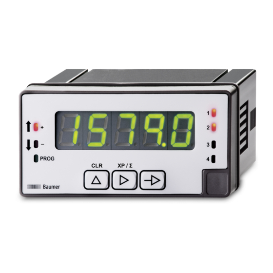
- Page 1 Operating Manual NE1218 EN-US Multifunction display...
-
Page 2: Table Of Contents
Operation mode pulse counter/ hour counter ............... 25 6.3.2 Operating mode frequency meter / tachometer ..............29 Configuration of the analog output ...................... 33 Control input configuration ........................34 Protect programming level via code....................36 Operating Manual NE1218 | V1... - Page 3 Block diagram of the configuration modules ..................12 Ill. 2 Duty cycle modulation (Duty Cycle) ....................18 Ill. 3 Limit value outputs - Time delay ......................30 Ill. 4 Limit value outputs - asymmetrical hysteresis..................30 V1 | NE1218 Operating Manual...
-
Page 4: About This Document
The illustrations are examples only. Deviations are at the discretion of Baumer at all times. The manual is a supplementary document to the existing product documentation. -
Page 5: Warnings In This Manual
Indicates a danger with low risk, which could lead to light or medium injury if not avoided. NOTE Indicates a warning of material damage. INFO Indicates practical information and tips that enable optimal use of the devices. V1 | NE1218 Operating Manual... -
Page 6: General Functionality
For universal counting inputs For tachometer and frequency Display range can be linearized Three control inputs, programmable Display of stabilization filter LED display, 5-digit, 3 colors, programmable Min, Max function DIN housing 96 x 48 mm Operating Manual NE1218 | V1... -
Page 7: Mounting The Multifunction Display
Instruction: a) Prepare the cut-out according to the dimensions. b) Push device (1) with seal (2) into the cut-out. c) Secure the device from behind using the clamping frame (3). d) Perform the electrical connection. V1 | NE1218 Operating Manual... -
Page 8: Connecting The Multifunction Display To Electricity
Pin assignment (at rear) Operating voltage (1) Phase Neutral Input signal (2) n.c. Sensor supply +20V Sensor supply +8.2V Sensor supply- / IN- Track B + Track A + n.c. Input 10-300 VAC Control input (3) Common Operating Manual NE1218 | V1... - Page 9 2 Four relays normally closed 1 normally closed 2 normally closed 3 normally closed 4 n.c. Common Analog output (5), optional (-) 4...20 mA / 0...10 V (+) 4...20 mA / 0...10 V V1 | NE1218 Operating Manual...
-
Page 10: Connection Examples
1 2 3 4 5 6 7 8 Display Encoder Encoder PNP/ 1 2 3 4 5 6 7 8 Signal A Signal B Display Contact input 10 - 300 VAC 1 2 3 4 5 6 7 8 Operating Manual NE1218 | V1... -
Page 11: Interfaces
Display as totalizer and time/ Digit/Function selection Button hour counter Reset Incrementing the selected Button digit LED PROG Programming mode active LED - Counter - Tachometer direction - LED + Counter + Tachometer direction + V1 | NE1218 Operating Manual... - Page 12 NOTICE Access to programming can be blocked at programming level. The various programming lines can then only be visualized but not changed. When entering the programming level, then appears instead of Operating Manual NE1218 | V1...
-
Page 13: Operating Functions
Namur sensor PNP sensor NPN sensor Inputs 2x90° TTL or HTL Contact input NPN Confirm with . Operating mode Use button to select the operating mode. Pulse counter Hour counter Frequency meter Tachometer Confirm with . V1 | NE1218 Operating Manual... -
Page 14: Operating Mode Pulse Counter
Counting operation is started via track A and stopped via track B. Track A and B edge-triggered Confirm with Use button to select the presentation on the display. 99999 hours 999 hours 59 minutes 999 minutes 99 seconds 999.99 seconds Confirm with Operating Manual NE1218 | V1... -
Page 15: Operating Mode Frequency Meter
Number of pulses per unit displayed Configurable from 1 to 99999 for speed display in rpm or m/min, cadence in strokes/min. Decimal digits Use button to select the position of the decimal point (number of deci- mal digits). Confirm with V1 | NE1218 Operating Manual... - Page 16 Displayed value 1 Displayed value 2 Measured Measured value 1 value 2 In these 2 modes, the display range is passing the point input frequency = 0 Hz. Operating Manual NE1218 | V1...
- Page 17 At nominal speed, the cycle time through the oven is 75 s at a wheel speed of 300 rpm. The pulse input frequency is 300 / 60 = 5 rpm and 5 x 50 pulses = 250 pulses per second. Programming: Display range = inverse [InP] = 250 [dSP] = 75 V1 | NE1218 Operating Manual...
- Page 18 Display range configuration to establish the relationship between the displayed values and the PWM duty cycle time. DC = 0% DC = 25% DC = 50% DC = 75% DC = 100% Ill. 2: Duty cycle modulation (Duty Cycle) Operating Manual NE1218 | V1...
-
Page 19: Configuration Of The Display
This function is used to configure the representation of the input signal on the display. Configuration Display INFO Only the configuration parameters for the selected input signal can be selected. Select the parameter to be configured with button Main counter XP Totalizer Σ Colors and display settings Confirm with V1 | NE1218 Operating Manual... -
Page 20: Used As Pulse Counter
An encoder with 1000 pulses/revolution is attached to the shaft end of a spindle with 5 mm pitch. To show the displacement in 1/100 mm, the factor is calculated 500 (1/100) / 1000 = 0.500. Operating Manual NE1218 | V1... - Page 21 Multiplying scaling factor Dividing scaling factor Confirm with Programmable from 00001 to 99999 Use button to select the position of the decimal point (number of deci- mal digits). Confirm with V1 | NE1218 Operating Manual...
-
Page 22: Used As Hour Counter
Display refresh time Programmable from 0.0 to 9.9 s Timeout Programmable from 0.1 to 99.9 s Time after which the display is set to zero if there is no pulse present at the input, Operating Manual NE1218 | V1... -
Page 23: Used As Tachometer
Similar to main counter XP (adding / subtracting) The count pulses are always added Confirm with Decimal digits Use button to select the position of the decimal point (number of deci- mal digits). Confirm with V1 | NE1218 Operating Manual... -
Page 24: Colors And Display Settings
Having elapsed this time the display will swich off. If the display is dark, the decimal at right will be on to indicate that the device is on. A press on any button will light up the display again in the selected color. Confirm each selection with Operating Manual NE1218 | V1... -
Page 25: Configuration Of The Limits
(Tps). if the counted value is ≥ limit and the output switching is programmed as latch signal (per- manent). V1 | NE1218 Operating Manual... - Page 26 Limits P1, P2, P3, P4 will be checked by the counter based on the offset value. If configured in [CSCdE] mode, the counter executes an automatic reset to the offset once the respective limit has been reached. The remaining outputs configured outputs as latch signals (permanent) are disabled. Operating Manual NE1218 | V1...
- Page 27 Main preset Confirm with Limit output enable Select with button when the limit output will be enabled. HIGH = Enabled at display value ≥ limit LOW = Enabled at display value ≤ limit Confirm with V1 | NE1218 Operating Manual...
- Page 28 The remaining parameters specified for this limit are not shown. Limit is active (programming and operation identical to P1) Trailing preset enabled Confirm with Trailing preset of main counter XP Adjustable from -99999 to 99999 trailing preset of totalizer Σ Operating Manual NE1218 | V1...
-
Page 29: Operating Mode Frequency Meter / Tachometer
Similar to individual target values, the alarm outputs will be enabled when the displayed value is reaching the user-defined limit. Configuration with High or Low defines output trigger either at display value ≥ or ≤ limit value. The outputs can be programmed with a time delay or with a hysteresis. V1 | NE1218 Operating Manual... - Page 30 Limit used as (only seen in tachometer mode) Main counter XP Totalizer Σ Programming and operation is identical to "Configuration as pulse counter or hour counter" Confirm with Limit frequency or tacho XP Adjustable from -99999 to 99999 Operating Manual NE1218 | V1...
- Page 31 S2 will be always enabled at a defined difference before or after limit P1. Chaging P1 does not require changing P2 as well. If limit P2 > 0, the preset value P1-P2. If limit P2 < 0, the preset is P1+P2, independent of offset > or < at P1. V1 | NE1218 Operating Manual...
- Page 32 The remaining parameters specified for this limit are not shown. Limit is active (programming and operation identical to P1) Trailing preset enabled Programming and operation is identical to P2 as trailing preset. Limit P4 is linked to limit P3. Confirm with Operating Manual NE1218 | V1...
-
Page 33: Configuration Of The Analog Output
This value displayed means the counter has reached the maximum limit re- spectively final value. Value adjustable from -99999 to 99999. Minimum limit of main counter XP The main counter starts evolving at this displayed value. Value adjustable from -99999 to 99999. Confirm with . V1 | NE1218 Operating Manual... -
Page 34: Control Input Configuration
This function is for control input configuration. Configuration Control inputs Control input connection 2 Control input connection 3 Control input connection 4 Confirm with Control input connection 2 Function (see table below) Value between 00 and 13 Confirm with Operating Manual NE1218 | V1... - Page 35 Quick access to parameterization of Offset, P1, P2, P3 or P4 Fictional presets if option is not available Simulating one of the 3 keys on the keypad Stop counter (*) Function edge active - F or static - S V1 | NE1218 Operating Manual...
-
Page 36: Protect Programming Level Via Code
1: configuration module protected Yes, all configuration modules are protected against modification and de- vice exits the programming level. Change code Change the code here, the new code is saved into the device and you exit programming level. Operating Manual NE1218 | V1... - Page 40 Baumer Germany GmbH & Co. KG Bodenseeallee 7 DE-78333 Stockach www.baumer.com...
Need help?
Do you have a question about the NE1218 and is the answer not in the manual?
Questions and answers