Table of Contents
Advertisement
Quick Links
Advertisement
Table of Contents

Related Manuals for Create WIND BALL


Summary of Contents for Create WIND BALL
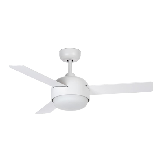
- Page 1 WIND BALL CEILING FAN WITH LIGHT ASSEMBLY MANUAL...
- Page 4 W I ND BALL To download this user guide in your language, visit our website: www.create-store.com/uk Para descargar el manual en su idioma, visite nuestra web: www.create-store.com/es Para baixar o manual no seu idiomas, visite nosso site: www.create-store.com/pt Pour télécharger le manuel dans votre langue, visitez notre site Web: www.create-store.com/fr...
-
Page 5: Table Of Contents
WIND BALL INDEX Box contents Step 1. Wood roof Step 1. Concrete ceiling Step 1. False ceiling Choice of height Step 2. Main body assembly Step 3. Earth connection Step 4. Driver connection Step 5. Blade assembly Step 6. Fitting the trim Step 7. -
Page 6: Box Contents
B OX C ONT EN T S FLOWER DRIVER REMOTE CONTROL LED PLATE (x3) REVERSIBLE BLADES LAMP COVER EMBELLISHER SUPPORT + ENGINE SHANK EXTENSION BAR MOUNTING BRACKET EMBELLISHER THE MOTOR (1) EXPANSION SCREWS SCREWS FOR SCREWS OF TRIM + ENGINE THE BLADES (2) WOOD SCREWS SPLICING TERMINALS... -
Page 7: Step 1. Wood Roof
STEP 1. WOO D CEI L I NG PARTS AND TOOLS NOT INCLUDED (2) WOOD SCREWS OPTIONAL ACCORDING TO CEILING TYPE Mark on the ceiling with a pencil the 4 If necessary, depending on the type of holes of piece K. ceiling, you will need to use a drill to make the hole in the wood. -
Page 8: Step 1. Concrete Ceiling
STEP 1. C ONC RE T E C EI L I NG PARTS AND TOOLS NOT INCLUDED (1) EXPANSION SCREWS Disassemble part M separating it into pieces. Ø8 mm Mark on the ceiling with a pencil the 2 cen- With the help of a drill, make the two cor- tral holes of piece K, using the same piece responding holes with an Ø8 mm drill bit. - Page 9 Place part K matching its holes with the Insert pieces M2, M3 and subsequently screws M1. Make sure the ceiling wires are the nut M4. placed on one side of piece K. Tighten piece M4 with a # 10 wrench, until Make sure that piece K is perfectly hooked you feel that it is well fixed.
-
Page 10: Step 1. False Ceiling
STEP 1. FALS E C EI L I NG PARTS AND TOOLS NOT INCLUDED FIXING SCREWS WITH SPRING LEVER Mark on the ceiling with a pencil the 2 cen- With the help of a drill, make the two cor- tral holes using piece K as a guide. responding holes. -
Page 11: Choice Of Height
C HO IC E OF HE IG HT Before you start, choose the desired height. (10cm+/-) You will have to choose between the height of the piece I wave J. · If you choose the height of the piece J, You must follow the instructions below. - Page 12 Snap the tilt bracket onto Tighten the two screws on Put the pin back in the piece the pin. the tilt bracket with the screwdriver. Secure the pin with the The piece J It would be locking piece so that it does ready to use.
-
Page 13: Step 2. Main Body Assembly
STEP 2. MA IN B ODY AS SEMB LY CHOOSE THE HEIGHT YOU NEED Remove the pin from the Enter the chosen bar through the hole in the part A. part I either J, depending on the chosen height. Insert the piece L As shown Once the pieces are inserted A and L, you must insert the in the picture. -
Page 14: Step 3. Earth Connection
Once the bar has been in- Put the locking piece on the Then replace the screws on serted, place the pin of the pin so that it does not come the part H so that the bar is part I/J so that it coincides out. -
Page 15: Step 4. Driver Connection
STEP 3. DR IVER C ON NECTI ON Remember to set the notch Put the tilt bracket into the Before continuing, check on the tilt bracket back so slot on the part K. that the central structure is that the piece fits snugly. well placed so that it does not fall. - Page 16 Select and connect the Once connected, place the You will need to attach the ground cables, including pieces O screwing them remaining wires from the the one for your installation. until they are secure. piece B and the phase and neutral cables of its instal- lation in the strip of the piece O, as it's shown in the...
-
Page 17: Step 5. Blade Assembly
Finally, with the help of a screwdriver, tighten the screws so that the piece is well fixed. STEP 4. BL A DE AS S EMB LY CHOOSE THE COLOR OF THE BLADE Remember that the blades are reversible, choose the color you like best and put it facing down. -
Page 18: Step 6. Fitting The Trim
STEP 5. FIT TING TH E TRI M Using a screwdriver, remove the 3 center screws from the Pass motor cables motor for later use. If these screws come separately in a through the hole on the side sealed bag, use them for this step. of the piece G. -
Page 19: Step 7. Led Board Connection
ST EP 6. LED BOAR D C O NNECTI O N Connect the part wires D to those of the fan joining the connections, each cable with its same color. Then attach the part D to the piece G with the help of the magnets so that it remains at- tached. -
Page 20: Step 8. Attaching The Lamp Cover
STE P 7. AT TAC H ING TH E L AM P C OVER Place the piece F on the fan by snapping it onto the motor and secure it by turning clockwise. Don't forget to check that the part G it is well attached. Once checked, you can connect the electricity and enjoy your new fan with light. -
Page 21: Blade Balancing Kit
B L ADE BAL A NC ING KI T Your ceiling fan may have blade swing problems when in operation due to irregularities in the blades or brackets. Also, incorrect system mounting or crooked bearings could cause additional problems. The following procedure is recommended to remedy these problems: 1.
Need help?
Do you have a question about the WIND BALL and is the answer not in the manual?
Questions and answers