Table of Contents
Advertisement
Quick Links
Instructions - Parts List
UniDrum
System
Bulk Supply System for 300 Gallon (1200 Liter) Magnadrums. For professional use only.
Not approved for use in explosive atmospheres or hazardous (classified) locations.
The UniDrum Supply System evacuates 300 gallon (1200 liter) magnadrums or other tote drums of the same size
and capacity. The UniDrum Supply System pumps and transfers flowable and highly viscous materials such as
sealant, adhesives, and sound deadeners from bulk drums with maximum efficiency.
The UniDrum Supply System is designed to work with other high pressure equipment to optimize material use.
See Technical Specifications on page 77 for Maximum Air Working Pressure
See page 4 for model information.
Important Safety Instructions
Read all warnings and instructions in this
manual and related manuals before
using the equipment. Save these
instructions.
UniDrum Left Hand Supply Unit
™
Supply
UniDrum Right Hand Supply Unit
309169ZAF
EN
Advertisement
Chapters
Table of Contents
Troubleshooting

Subscribe to Our Youtube Channel
Related Manuals for Graco UniDrum C59784


Summary of Contents for Graco UniDrum C59784
- Page 1 Instructions - Parts List ™ UniDrum Supply System 309169ZAF Bulk Supply System for 300 Gallon (1200 Liter) Magnadrums. For professional use only. Not approved for use in explosive atmospheres or hazardous (classified) locations. The UniDrum Supply System evacuates 300 gallon (1200 liter) magnadrums or other tote drums of the same size and capacity.
-
Page 2: Table Of Contents
Contents Pneumatic Logic Panel Service ....31 Related Manuals ......3 Filter/Element Replacement . -
Page 3: Related Manuals
C59794 - 47:1 Right Hand Supply Unit, with Graco Standard Warranty....82 XL10000 carbon steel pump ... . 55... -
Page 4: Models
Models Models The UniDrum Supply Units listed below are covered in this manual. For specific pump information, refer to the chart in Servicing the Pumps on page 35. Tandem Supply Unit Max. Outlet Max. Fluid Pump System Depressurization Platen Part No. Pump Ratio Pressure... -
Page 5: Warnings
Check hoses and couplings daily. Replace worn or damaged parts immediately. • Use only Graco approved hoses. Do not remove any spring guard that is used to help protect the hose from rupture caused by kinks or bends near the couplings. - Page 6 Warnings WARNING ELECTRIC SHOCK HAZARD This equipment must be grounded. Improper grounding, setup, or usage of the system can cause electric shock. • Turn off and disconnect power at main switch before disconnecting any cables and before servicing or installing equipment. •...
- Page 7 Warnings WARNING SPLATTER HAZARD Hot or toxic fluid can cause serious injury if splashed in the eyes or on skin. During blow off of platen, splatter may occur. • Use minimum air pressure when removing platen from drum. TOXIC FLUID OR FUMES HAZARD Toxic fluids or fumes can cause serious injury or death if splashed in the eyes or on skin, inhaled, or swallowed.
-
Page 8: Uncrating The System
Overview The UniDrum Supply System was carefully packaged Installation Overview for shipment by Graco. When the system arrives, perform the following procedure to uncrate the system. The location of the UniDrum should allow for easy loading and unloading of the 300 gallon (1200 liter) NOTICE magnadrum or other tote drums with a forklift. -
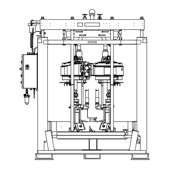
Page 9: Component Identification
Component Identification Component Identification NOTE: F . 1 shows the typical UniDrum Supply System equipped with XL 10000™ air motors. UniDrum Supply System To drum empty valve supply * Remove these lines to run systems independently A -- Left Hand Unit B -- Right Hand Unit . -
Page 10: Pneumatic Logic Panel, 243559
Component Identification Pneumatic Logic Panel, 243559 24K173 Panel Shown . 2: Pneumatic Logic Panel 309169ZAF... - Page 11 Component Identification 9327A . 3: Pneumatic Logic Panel Interior 309169ZAF...
- Page 12 Component Identification Pneumatic Logic Panel Switches and Indicators Use the table and F . 2 when operating the switches and reading the indicators on the Pneumatic Logic Panel (G). Ref. Button/Switch/Guage What it Does PUMP NO. 1 PRESSURE Air Gauge Indicates the air outlet pressure setting from Pump No.
-
Page 13: General Description
Contact your Graco distributor for help in choosing accessories to suit your • Bleed Sticks (H) are removed to allow air trapped particular needs. - Page 14 Component Identification In the OPEN position, the vents open after a short delay and remain open to facilitate cleaning. The selector should be returned to the AUTO setting immediately after cleaning is complete. If the valve is left OPEN, the vents may open when the RAM POSITION Switch (AG) is placed in the UP position, and material may flow past the vents onto the top of the...
-
Page 15: Installation
Data presented here pertains to the system only. • Have all system and subassembly documentation available during installation. • Be sure that all non-Graco supplied hoses are adequately sized and pressure-rated to meet the system requirements. 309169ZAF... -
Page 16: Installing The Unidrum
Installation Installing the UniDrum Air and fluid hoses: use only electrically conductive hoses. To install the UniDrum, follow the procedure below. Air compressor: follow manufacturer’s Refer to Technical Specifications on page 77 for ram recommendations. mounting and clearance dimensions. Spray gun / Dispense valve: ground through 1. -
Page 17: Connecting The Air Supply Lines To The Unidrum17
Installation Connecting the Air Supply Lines to the UniDrum Perform the following procedure to connect the input Have a qualified technician connect both Supply Units air supply lines to the UniDrum Supply System. to an air supply source that has the following required ratings: Connecting Air Supply Lines to the Supply Units... -
Page 18: Connecting Output Hose To The Pumps
Installation Connecting Output Hose to the NOTICE Pumps There must be a minimum of 10 feet (3 m) of fluid supply hose on the outlet to prevent damage to the This procedure describes how to connect the fluid unit. output hoses to the two Pumps. It is the customer’s responsibility to have the fluid supply hose already NOTE: The fluid supply hose must move freely without installed and ready for connection to the Pumps. -
Page 19: Operation
Operation Operation Prepare the Operator To load the drum into the Supply Unit (A, B), the Follower Plate (D) must be raised and the Bleed Stick (H) removed at the Supply Unit. The Follower Plate (D) All persons who operate the equipment must be trained is lowered by the operator directly into the drum, and in the safe, efficient operation of all system components the bleed sticks are replaced. -
Page 20: Flushing The System Before Initial Use
Operation Flushing the System Before oil from the system. If necessary, check with the material supplier for a recommended flush material. Initial Use 4. Before flushing, be sure the entire system and Flushing the system before its initial use can prevent flushing drums are properly grounded. -
Page 21: Initial System Startup Procedure
Follower Plate to reduce the risk of pinching or 3. Fill the packing nut/wet cup on both Pumps 1/3 full amputating hands or fingers. with Graco throat seal liquid (p/n 206995). Refer to your specific pump manual for details. NOTICE The use of a non-compatible lubricant can cause 4. - Page 22 Operation Adjusting the Pump Regulators NOTE: Both Pumps must operate at the same cycles per minute rate to prevent the occurrence of uneven Do not set the R3 Regulator higher than 5 to 10 drum evacuation. psi (0.035 to 0.07 MPa, 0.35 to 0.7 bar). Setting the R3 Regulator pressure higher than NOTE: For the maximum air input pressure for each recommended can cause the Follower Plate (D) to...
- Page 23 Operation Preventing Pump Cavitation Adjusting the Empty/Low Limit Switches NOTE: Cavitation occurs when the Pump cylinder did NOTE: When the low limit switch is activated, the not fully load with material on the upstroke, and a cavity Pumps are normally turned off automatically by a forms in the material after the Pump changes to the customer-supplied control, and a second set of Pumps downstroke.
-
Page 24: Changing Empty Drums
Operation Changing Empty Drums 7. Being careful not to damage the Follower Plate (D) wipers, wipe or scrape any material buildup from the Follower Plate (D) and wipers, and properly NOTE: After the automatic Pump crossover has taken dispose of the waste material. place, immediately replace the empty drum with a new, full drum. - Page 25 Operation g. Wipe any excess material from the Pump bleed valve outlet to prevent material from drying and curing. Cover the Pump bleed valve outlet with a material-compatible grease. Before lowering the Follower Plate (D) into the drum, make sure that nothing is between the Follower Plate NOTE: If the Pump bleed valve has a grease zerk, apply and the drum, or between the ram tie bar and the a material-compatible grease into the zerk fitting until...
-
Page 26: Daily System Startup
Operation Daily System Startup This procedure is normally provided by the integrator. System Shutdown This procedure is normally provided by the integrator. Stopping the System To stop the system, close the main air shutoff valve (see F . 9) to the Supply Unit. Restarting the System To restart the system, perform the following steps: 1. -
Page 27: Pressure Relief Procedures
Pressure Relief Procedures Pressure Relief Procedures Fluid Pressure Relief Procedure These procedures describe how to relieve pressure from the system. This procedure describes how to relieve pressure on the Follower Plate (D) and in the Pumps (C). Use this Follow the Pressure Relief Procedure whenever procedure whenever you shutoff the Pumps and before you see this symbol. -
Page 28: Pneumatic Pressure Relief Procedure
Pressure Relief Procedures Pneumatic Pressure Relief Procedure Main Air Inlet This procedure describes how to relieve pressure on the Pneumatic Logic Panel (G) and cylinders. Use this procedure whenever you perform ram assembly service on the piston rod seal or the ram piston. 1. -
Page 29: Maintenance
Maintenance Maintenance Preventative Maintenance Cleaning the System Schedule NOTICE The operating conditions of your particular system Cleaning the system after using it can prevent determine how often maintenance is required. Establish material contamination, which may cause the material a preventive maintenance schedule by recording when to fail or perform poorly. -
Page 30: Wiper Lubrication
Maintenance 4. It is recommended to clean the platen between each drum change, or as recommended by your facility’s maintenance plan. Use a long-handled flat-bladed ice scraper if it is necessary to scrape the bottom of the Follower Plate (D). To avoid serious injury, do not put your hands between the plate and the drum. -
Page 31: Pneumatic Logic Panel Service
Pneumatic Logic Panel Service Pneumatic Logic Panel Service Filter/Element Replacement Filter Removal 3. Turn the air filter counterclockwise to unscrew the The air filter is located between the air supply source filter from its mounting. and the Pneumatic Logic Panel (G). See F . -
Page 32: Ram Assembly Service
Ram Assembly Service Ram Assembly Service Piston Rod Seal Service Ring, Seal Guard Sleeve Ring 1. Relieve the air pressure. Follow the Pneumatic Pressure Relief Procedure on page 28. 2. Remove the four nuts and lockwashers holding the tie bar to the rods. Remove the tie bar. O-ring 3. -
Page 33: Ram Piston Service
Ram Assembly Service Ram Piston Service Ring O-ring 1. Relieve the air pressure. Follow the Pneumatic O-ring Pressure Relief Procedure on page 28. 2. Remove the tie bar as explained in the Piston Rod Band Seal Service section on page 32. 3. -
Page 34: Low/Empty Limit Switch Replacement
Ram Assembly Service Low/Empty Limit Switch 2. Shut off power to the Pneumatic Logic Panel (G). Replacement NOTE: When raising and lowering the Follower Plate (D), make sure the unit is unobstructed overhead to avoid interference with other objects. Switch Removal During operation, keep hands and fingers away from 3. -
Page 35: Replacing Wipers
Ram Assembly Service Switch Replacement setscrew, pull the end of the strapping through the clamp (413b) and remove the wiper. 7. Install the new limit switch (305) on the limit bracket (306) using the fasteners. 4. Slide the strapping (413a) through the new wiper (412). - Page 36 Ram Assembly Service Detail A Detail B 413c 413b 413a 02949 02946 413b 413a 413b 413c Detail C Slide the clamp onto the strapping and bend the strapping back approximately 3 in. (76 mm). Turn clockwise to apply tension. Cut the strapping and bend it 413a 05712 .
-
Page 37: Pump Removal
Pump manual to find the weight of the Pump switch back to HOLD/NEUTRAL. being serviced. For example, Graco XL 10000™ 45:1 SST Pump (24Y208) weighs 236 lb (106 kg) per manual 16. Move the Pump assembly to a suitable work area 308148. -
Page 38: Recycling And Disposal
Recycling and Disposal Recycling and Disposal End of Product Life At the end of the product’s useful life, dismantle and recycle it in a responsible manner. • Perform the Pressure Relief Procedures. • Drain and dispose of fluids according to applicable regulations. -
Page 39: Troubleshooting
Troubleshooting Troubleshooting Follow Pressure Relief Procedures, page 27 and 28, before checking or repairing the UniDrum Supply System. NOTE: Check all possible problems and causes before disassembling the equipment. Ram Assembly Troubleshooting Problem Cause Solution Ram won’t raise or lower Closed main air shutoff valve or Open air valve, clear air line clogged air line... -
Page 40: Pump Troubleshooting
Troubleshooting Pump Troubleshooting For additional information about the displacement Pump, refer to Related Manuals on page 3 to find the applicable instruction manual. Problem Cause Solution Air is trapped in Pump. Bleed air from the Pumps and prime Rapid downstroke or upstroke using the procedure described in steps 16a - 16h on page 25. -
Page 41: Air Motor Troubleshooting
Troubleshooting Air Motor Troubleshooting For additional information about the air motor, refer to Related Manuals on page 3 to find the applicable instruction manual. Problem Cause Solution Air motor will not shift directions, Main air valve spool is dirty or Clean/rebuild main air valve. -
Page 42: Pneumatic Logic Panel Troubleshooting
Troubleshooting Pneumatic Logic Panel Troubleshooting Problem Cause Solution Ram will not move up or down. Main air valve on box is not open. Open valve. Air supply to unit is not on. Turn on air supply. Ram will not move up. Direction valve is not in the UP Set direction valve to the UP position. -
Page 43: Parts
Parts Parts C59784 - 20:1 Left Hand Supply Unit, with King carbon steel pump C59785 - 20:1 Right Hand Supply Unit, with King carbon steel pump 130,148 124,125,126 133,125 309169ZAF... -
Page 44: C59784 - 20:1 Left Hand Supply Unit, With King Carbon Steel Pump
Parts 127,141 C59784 - 20:1 Left Hand Supply Unit, with King carbon steel pump C59785 - 20:1 Right Hand Supply Unit, with King carbon steel pump Ref. Part Description Qty. Ref. Part Description Qty. 196073 CLAMP 222833 PUMP,KING,QUIET,20:1 109495 PACKING,O-RING C20490 FITTING,NIPPLE,HEX 237569 WIRE,ASSY,25 FT C20489 FITTING,NIPPLE... -
Page 45: C58461 - 35:1 Left Hand Supply Unit, With Xl10000 Carbon Steel Pump
Parts C58461 - 35:1 Left Hand Supply Unit, with XL10000 carbon steel pump C58462 - 35:1 Right Hand Supply Unit, with XL10000 carbon steel pump 257,252 208,209 209,210,211 205,210 209,210,211 222 248 223 309169ZAF... -
Page 46: C58461 - 35:1 Left Hand Supply Unit, With Xl10000 Carbon Steel Pump
Parts 212,217 C58461 - 35:1 Left Hand Supply Unit, with XL10000 carbon steel pump C58462 - 35:1 Right Hand Supply Unit, with XL10000 carbon steel pump Ref. Part Description Qty. Ref. Part Description Qty. 521850 VALVE, check PINS, safety, kit, see page 66 C38324 FITTING, elbow, street C58360... -
Page 47: 24P842, 47:1 Left Hand Supply Unit, With Xl 10000 Stainless Steel Pump
Parts 24P842, 47:1 Left Hand Supply Unit, with XL 10000 stainless steel pump 24P843, 47:1 Right Hand Supply Unit, with XL 10000 stainless steel pump 360,352 308,309 309,310,311 305,310 309,310,311 309169ZAF... -
Page 48: 24P842, 47:1 Left Hand Supply Unit, With Xl 10000 Stainless Steel Pump
Parts 312,317 24P842, 47:1 Left Hand Supply Unit, with XL 10000 stainless steel pump 24P843, 47:1 Right Hand Supply Unit, with XL 10000 stainless steel pump Ref. Part Description Qty. Ref. Part Description Qty. C38324 FITTING, elbow, street PINS, safety, kit, see page 66 233058 HOSE, coupled C58360... -
Page 49: 246983 - 47:1 Left Hand Supply Unit, With Xl10000 Stainless Steel Pump With Silicone Nitride Balls
Parts 246983 - 47:1 Left Hand Supply Unit, with XL10000 stainless steel pump with silicone nitride balls 246984 - 47:1 Right Hand Supply Unit, with XL10000 stainless steel pump with silicone nitride balls 442,431 412,405 405,406,407 408,406 405,406,407 309169ZAF... -
Page 50: 246983 - 47:1 Left Hand Supply Unit, With Xl10000 Stainless Steel Pump With Silicone Nitride Balls
Parts 403,404 246983 - 47:1 Left Hand Supply Unit, with XL10000 stainless steel pump with silicone nitride balls 246984 - 47:1 Right Hand Supply Unit, with XL10000 stainless steel pump with silicone nitride balls Ref. Part Description Qty. Ref. Part Description Qty. -
Page 51: 249154 - 35:1 Left Hand Supply Unit, With Xl10000 Stainless Steel Pump With Silicone Nitride Balls
Parts 249154 - 35:1 Left Hand Supply Unit, with XL10000 stainless steel pump with silicone nitride balls 249155 - 35:1 Right Hand Supply Unit, with XL10000 stainless steel pump with silicone nitride balls 531,542 512,505 505,506,507 508,506 505,506,507 309169ZAF... -
Page 52: 249154 - 35:1 Left Hand Supply Unit, With Xl10000 Stainless Steel Pump With Silicone Nitride Balls
Parts 534,535 503,504 249154 - 35:1 Left Hand Supply Unit, with XL10000 stainless steel pump with silicone nitride balls 249155 - 35:1 Right Hand Supply Unit, with XL10000 stainless steel pump with silicone nitride balls Ref. Part Description Qty. Ref. Part Description Qty. -
Page 53: C58607 - 56:1 Left Hand Supply Unit, With King Carbon Steel Pump
Parts C58607 - 56:1 Left Hand Supply Unit, with King carbon steel pump C58608 - 56:1 Right Hand Supply Unit, with King carbon steel pump 642,646,641 645,646,642 309169ZAF... -
Page 54: C58607 - 56:1 Left Hand Supply Unit, With King Carbon Steel Pump
Parts 656,657 628,629 634,654 C58607 - 56:1 Left Hand Supply Unit, with King carbon steel pump C58608 - 56:1 Right Hand Supply Unit, with King carbon steel pump Ref. Part Description Qty. Ref. Part Description Qty. 118854 VALVE, ball, high pressure PINS, safety, kit, see page 66 070408 SEALANT, pipe, stainless... -
Page 55: C59793 - 47:1 Left Hand Supply Unit, With Xl10000 Carbon Steel Pump
Parts C59793 - 47:1 Left Hand Supply Unit, with XL10000 carbon steel pump C59794 - 47:1 Right Hand Supply Unit, with XL10000 carbon steel pump 757,752 708,709 709,710,711 705,710 709,710,711 309169ZAF... -
Page 56: C59793 - 47:1 Left Hand Supply Unit, With Xl10000 Carbon Steel Pump
Parts 754,755 712,717 C59793 - 47:1 Left Hand Supply Unit, with XL10000 carbon steel pump C59794 - 47:1 Right Hand Supply Unit, with XL10000 carbon steel pump Ref. Part Description Qty. Ref. Part Description Qty. 233058 HOSE, coupled PINS, safety, kit, see page 66 521975 FITTING, union, pipe 233050... -
Page 57: C58338 - 71:1 Left Hand Supply Unit, With Xl10000 Carbon Steel Pump
Parts C58338 - 71:1 Left Hand Supply Unit, with XL10000 carbon steel pump C58601 - 71:1 Right Hand Supply Unit, with XL10000 carbon steel pump 860,852 808,809 809,810,811 805,810 809,810,811 309169ZAF... -
Page 58: C58338 - 71:1 Left Hand Supply Unit, With Xl10000 Carbon Steel Pump
Parts 854,855 812,817 C58338 - 71:1 Left Hand Supply Unit, with XL10000 carbon steel pump C58601 - 71:1 Right Hand Supply Unit, with XL10000 carbon steel pump Ref. Part Description Qty. Ref. Part Description Qty. 521975 FITTING, union, pipe PINS, safety, kit, see page 66 118854 VALVE, ball, high pressure 233050... -
Page 59: 24R875 - 10:1 Left Hand Supply Unit, With Nxt Carbon Steel Pump
Parts 24R875 - 10:1 Left Hand Supply Unit, with NXT carbon steel pump 24R876 - 10:1 Right Hand Supply Unit, with NXT carbon steel pump 930,948 309169ZAF... -
Page 60: 24R875 - 10:1 Left Hand Supply Unit, With Nxt Carbon Steel Pump
Parts 946,947 24R875 - 10:1 Left Hand Supply Unit, with NXT carbon steel pump 24R876 - 10:1 Right Hand Supply Unit, with NXT carbon steel pump Ref. Part Description Qty. Ref. Part Description Qty. 070408 SEALANT, pipe, stainless PINS, safety, kit, see page 66 steel 24T263 ELEVATOR, RAM 300 gal RH... -
Page 61: Pneumatic Logic Panel, 243559
Parts Pneumatic Logic Panel, 243559 1015 1063 1013 1071 1010 1004 1016 1017 1006 1039 . 20 309169ZAF... - Page 62 Parts 9045a 9054a 9009a 9053a 9055 9039a 9014a 9012b 9012a 9001b 9002b . 21 309169ZAF...
- Page 63 Parts Pneumatic Logic Panel, 243559 Ref. Part Description Qty. 1004 517315 VALVE, 3 way, button, palm 1005a 125441 VALVE, air, pilot, 4-way, 5 port 1006 125504 VALVE, pneumatic, 3 position 1008a 125464 VALVE, impulse, one shot 1009a 125516 VALVE, pneumatic, logic, OR 1010 125506 VALVE, pneumatic, regulator...
-
Page 64: Follower Plate, 233041
Parts Follower Plate, 233041 4001 4002* 4007* 4003* 4011* 4008* 4013b 4009* 4013c 4004* 4005* 4006* 4010* DETAIL A SEE DETAIL A 4018 DETAIL B 4022 4023 4019, 4020 4021 4017 4013a 4012 4016 SEE DETAIL B . 22 309169ZAF... - Page 65 Parts Follower Plate, 233041 Ref. Part Description Qty. 4001 233040 PLATE, ram 4002* 115782 CYLINDER, air 4003* 196052 SPACER 4004* 196053 PLATE 4005 517286 PLUNGER 4006* 115783 BOLT, hex hd 4007* 196051 SPACER 4008* 100333 SCREW, cap, hex hd 4009* 100016 WASHER, lock;...
-
Page 66: Safety Pin Maintenance Kit, 26B772
Parts Safety Pin Maintenance Kit, 26B772 Left-Handed Unit Shown 8004 8011 8019 8020, 8022 8021 8003 8002 8006, 8007 8015 8018 8011,8013, 8017,8015 8009 8001 8019 8014 8008 8010 8005 8012, 8004 8013 . 23 309169ZAF... - Page 67 Parts Safety Pins, 26B772 Ref. Part Description Qty. 8001 26B769 BRACKET, cylinder support 8002 18D250 TUBE, support, outer 8003 18D251 TUBE, support, inner 8004 18D249 PLATE, base, lock out 8005 133303 STRAP, pipe, 2 in. 8006 16Y456 PIN, safety, hitch 8007 15G945 CABLE, lanyard, 24 in.
-
Page 68: Elevator Assembly, 248126 And 248127
Parts Elevator Assembly, 248126 and 248127 9034, 9035 See detail A 9057 9055 9052 9054 9058 9059 9060 9002 9065 9053 9076 9022 9081 9077 9078 9082 9001 9048 9087 9090 9020 9050 9083 9074 9051 9003 9095 9085 See detail B 9093, 9094 9074 9010... - Page 69 Parts 9088 9079, 9080, 9013 See Detail C 9013, 9006 9042 9074 9043 9014 9090 9087 9073 9056 9047 9064 9074 9066, 9092 Detail C 9068 9063 9045 9103 9016, 9017 9046 9070 9061 9072 9069 9074 9062 9070 See Detail D 9090 Detail D 9076...
- Page 70 Parts Elevator Assembly, 248126 and 248127 Ref. Part Description Qty. Ref. Part Description Qty. 9060 224040 VALVE, runaway 9001 617206 ELEVATOR, weldment 300 9061 C19438 ELBOW, 90° gallon 9062 C19630 NIPPLE, 1 npt 9002 617204 CARRIAGE, weldment 300 gallon 9063 113532 ELBOW, fitting (f) 9003...
-
Page 71: Elevator Assembly, 233050, 233066, 24T263, 24T264
Parts Elevator Assembly, 233050, 233066, 24T263, 24T264 2060 See detail A 2034, 2035 2057 2055 2052 2065 2058 2054 2059 2053 2002 2078 2076 2077 2081 2106, 2105 2082 2087 2001 2020 2083 2096 See detail B 2095 2085 2025 2023 2024 2010... - Page 72 Parts 2014 See Detail C 2100,2101 2079, 2080, 2100 2090 2042 2074 2074 2074 2064 2056 2073 2043 2014 2066, 2092 2099 2068 Detail C 2063 2103 2016, 2017 2070 2045 2072 2046 2070 See Detail D 2061 2069 2062 2074 2044 2015...
- Page 73 Parts Elevator Assembly, 233050, 233066, 24T263, 24T264 Ref. Part Description Qty. Ref. Part Description Qty. 2070 C19032 UNION PINS, safety, kit, see page 66 2072 112859 FILTER, air, 1 npt 2001 617206 ELEVATOR, weldment 300 gallon 2073 C20378 FITTING, branch y 2002 617204 CARRIAGE, weldment 300 gallon...
-
Page 74: Recommended Spare Parts
Recommended Spare Parts Recommended Spare Parts Spare Parts for Pump and Air Motor Refer to the appropriate manual listed in Related Manuals on page 3. Spare Parts for Ram Plate Assembly The customer should maintain an inventory of the spare parts (per unit) listed below. -
Page 75: Pneumatic Diagram
Pneumatic Diagram Pneumatic Diagram DRUM EMPTY PUMP AIR (BOTTOM) (TOP) (MIDDLE) PUMP AIR OFF VENT AUTO OPEN PILOT RAM CONTROL RAM UP SAFETY RAISE A(BOT) A(TOP) LOWER PILOT DRUM IN DRUM IN POSITION POSITION MAIN AIR ‘IN’ CONNECTION DESCRIPTION TUBING NUMBER LEGEND AIR SUPPLY FOR DRUM EMPTY DIRECTIONAL VALVE... - Page 76 Pneumatic Diagram 309169ZAF...
-
Page 77: Technical Specifications
Technical Specifications Technical Specifications Models C59784, C59785 UniDrum Supply System Metric Supply Units (LH and RH) Compressed air requirement 80 psi (maximum) (5.5 bar, 0.55 MPa), 450 cfm Main air inlet size 1 in. npt(f) Overall weight (approximate) 3950 lb 1792 kg King Pumps Ratio... -
Page 78: Models C58607, C58608
Technical Specifications Models C58607, C58608 UniDrum Supply System Metric Supply Units (LH and RH) Compressed air requirement 80 psi (maximum) (5.5 bar, 0.55 MPa), 450 cfm Main air inlet size 1 in. npt(f) Overall weight (approximate) 3950 lb 1792 kg King Pumps Ratio 56:1 fluid to air power ratio... -
Page 79: Models C58338, C58601
Technical Specifications Models C58338, C58601 UniDrum Supply System Metric Supply Units (LH and RH) Compressed air requirement 80 psi (maximum) (5.5 bar, 0.55 MPa), 450 cfm Main air inlet size 1 in. npt(f) Overall weight (approximate) 3950 lb 1792 kg LX 10000 Pumps Ratio 71:1 fluid to air power ratio... -
Page 80: Models C58461, C58462, 249154, 249155
Technical Specifications Models C58461, C58462, 249154, 249155 UniDrum Supply System Metric Supply Units (LH and RH) Compressed air requirement 80 psi (maximum) (5.5 bar, 0.55 MPa), 450 cfm Main air inlet size 1 in. npt(f) Overall weight (approximate) 3950 lb 1792 kg XL 10000 Pumps Ratio... -
Page 81: Models 246983, 246984, C59793, C59794
Technical Specifications Models 246983, 246984, C59793, C59794 UniDrum Supply System Metric Supply Units (LH and RH) Compressed air requirement 80 psi (maximum) (5.5 bar, 0.55 MPa), 450 cfm Main air inlet size 1 in. npt(f) Overall weight (approximate) 3950 lb 1792 kg XL 10000 Pumps Ratio... -
Page 82: Graco Standard Warranty
With the exception of any special, extended, or limited warranty published by Graco, Graco will, for a period of twelve months from the date of sale, repair or replace any part of the equipment determined by Graco to be defective.
Need help?
Do you have a question about the UniDrum C59784 and is the answer not in the manual?
Questions and answers