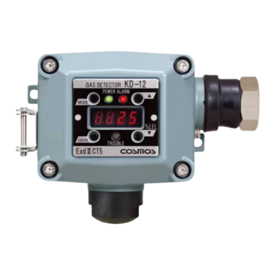
New Cosmos Electric KD-12 HART Series Instruction Manual
Diffusion type gas detector
Hide thumbs
Also See for KD-12 HART Series:
- Instruction manual (40 pages) ,
- Instruction manual (38 pages) ,
- Instruction manual (40 pages)
Table of Contents
Advertisement
Quick Links
Diffusion Type Gas Detector
KD-12 HART Series
Instruction Manual
Keep this manual for easy reference.
Carefully read this manual prior to use.
This manual describes the standard model. If your unit contains customer-specific
options, the delivery specifications will supersede this manual.
New Cosmos Electric Co., Ltd.
Instruction Manual No.
GAE-119-08
September 2022
Advertisement
Table of Contents

Related Manuals for New Cosmos Electric KD-12 HART Series


Summary of Contents for New Cosmos Electric KD-12 HART Series
- Page 1 Keep this manual for easy reference. Carefully read this manual prior to use. This manual describes the standard model. If your unit contains customer-specific options, the delivery specifications will supersede this manual. New Cosmos Electric Co., Ltd. Instruction Manual No. GAE-119-08 September 2022...
- Page 2 Unit Dimensions and Sensor Unit Replacement Components Pages 34 and 35 Pages 4 to 6 Wiring Display and Operation Modes Pages 13 to 17 Page 19 Maintenance, Operational Troubleshooting Checks/Procedures Page 36,37 Pages 25 to 33...
-
Page 3: Table Of Contents
Table of Contents Introduction ........................1 General Precautions ...................... 2 Package Contents ......................3 Unit Dimensions and Components ................4 4.1 Exterior Appearance ..................... 4 4.2 Display and Controls ..................... 5 4.3 Terminal Block ....................... 6 Installation ........................7 5.1 Procedure ........................7 5.2 Typical Installation Locations .................. -
Page 4: Introduction
Introduction Thank you for purchasing the New Cosmos KD-12 HART series Diffusion Type Gas Detector. Please read the enclosed instruction to ensure safe and reliable operation. This gas detection unit detects various gas types including combustible gases. This unit is intended for use in industrial facilities (e.g. -
Page 5: General Precautions
General Precautions Carefully read this manual prior to use. To ensure safe operation, follow the precautions below. DANGER Be sure to ground the detector to prevent electric shocks. In the event of a gas leak alarm, follow safety procedures in accordance with your company's regulations. -
Page 6: Package Contents
Package Contents This product is packed and shipped with the utmost care. If any items are missing or damaged, please contact New Cosmos or its distributor for replacement. Package Contents Optional Items Gas detector Protective cover Horizontal type (KW-41A) Accessory kit Vertical type (KW-42A) M5x15 screws for wall-mounting: 2 pcs 2B pole mounting bracket (PB-1) -
Page 7: Unit Dimensions And Components
Unit Dimensions and Components 4.1 Exterior Appearance (Dimensions are in mm) Item Component Description/Function Case cover Case Incorporates a built-in gas sensor. Sensor unit Sensor guard Protects the sensor unit. Used for grounding the frame. Earth terminal (external) Indicate the status of the unit: Status LEDs (3 places) power (green), alarm (red), and fault (amber) Insert the magnetic stick into each magnetic switch... -
Page 8: Display And Controls
4.2 Display and Controls Magnetic Switches Use the magnetic stick (MJ-1) to operate the magnetic switches. Item Component Description/Function Changes the operation mode or cancels the current [MODE] switch operation. [ENTER] switch Confirms a setting or executes an operation. [UP] switch Increases the parameter value. -
Page 9: Terminal Block
4.3 Terminal Block Terminal Block Earth Terminal (Internal) Gasket Sensor Connector Item Name Description/Function 24 V (+) Power supply voltage (positive) Power supply voltage (-) and analog signal (-) common Signals 4-20mA analog and HART signals External relay contact Earth terminal Used for grounding the frame. -
Page 10: Installation
Installation 5.1 Procedure WARNING The cable gland and blanking elements shall be ATEX/UKEx/IECEx-certified as “Flameproof Enclosure ‘db’”, and shall meet the special conditions below. If used in an ATEX hazardous area, an ATEX-certified cable gland must be used according to EN IEC 60079-0:2018 and EN 60079-1:2014. - Page 11 CAUTION Be careful not to damage the gas detector during installation. Keep joint surfaces clean and free from any damage. Contaminates such as scratches, fingerprints, dirt and oil may adversely affect the explosion-proof characteristics of the device. Do not install the gas detector in the following conditions - Ambient temperature is outside of the specified operating temperature range (10C to 50C).
- Page 12 Secure the gas detector to the wall by tightening the two M5 screws (included) through the mounting holes. Attach the protective cover (not included) when installing the detector outdoors. Mount the detector with a 2B pole mounting bracket (not included) when mounting the detector to a 2B pole.
- Page 13 Maintain a distance of 50cm or more between the front of the detector and any other object during installation and operation. Maintain a distance of 50cm or more When installing this diffusion-type gas detector in a high location, or on a ceiling, make sure to leave enough space below the detector to allow for inspection or maintenance activities.
-
Page 14: Typical Installation Locations
5.2 Typical Installation Locations Install the gas detector in a place where gas is expected to accumulate. Places where gas is likely to accumulate. Gas detector Doors and windows Roof fan (Inlets and outlets) (Outlet) Entrance (Inlet) Plan View Side View Indoor Installation Partition... -
Page 15: Installation Of Optional Parts
5.3 Installation of Optional Parts Protective Cover (190) (90) (90) (190) M3 screw(1 place) M3 screw(1 place) (190) (190) (Dimensions are in mm) Horizontal Type (KW-41A) Vertical Type (KW-42A) DANGER Secure the protective cover with M3 screw (1 place) when installing the gas detector in a place subject to strong winds. -
Page 16: Wiring
Wiring 6.1 Guideline Use explosion-proof wiring when installing the detector in a hazardous area. WARNING The cable gland and blanking elements shall be ATEX/UKEx/IECEx-certified as “Flameproof Enclosure ‘db’”, and shall meet the special conditions for safe use. Installation in strict accordance to the Section 5.1 “Procedure” is required. CAUTION ... -
Page 17: Wiring/Connection
6.2 Wiring/Connection WARNING Before opening the case cover of the gas detector, be sure to eliminate possible source of ignition. Disconnect the power supply to the detector and all devices connected to it (e.g. indicator unit and signal converter). ... - Page 18 The specifications for single wires/twisted wires/pins to be connected to the terminal block are given below. Prepare wires/pins that comply with these specifications. Stripped wire length (L) = 7mm - Single wire outer diameter: 0.2 mm2 to 4 mm - Twisted wire outer diameter: 0.2 mm to 2.5 mm - Pin outer diameter without plastic sleeve...
-
Page 19: Terminal Block Wiring Procedure
6.3 Terminal Block Wiring Procedure CAUTION Do not apply the power supply to the gas detector until wiring is completed and the case cover is closed. Do not touch or let any tool (e.g. screwdriver, wrench) touch the inside surface of the case or case cover, keep joint surfaces clean and free from any damage. -
Page 20: Precautions Before Use
(6) Remove the screwdriver from the slot to close it. This will securely connect the wire to the terminal. (7) Check that these three wires are secure in their corresponding terminals. (8) Additional wiring for the external relay contact can use the slots marked “ZA ” and “ZC ” . (9) Close the case cover. -
Page 21: Display At Power-Up (Warm-Up)
Display at Power-up (Warm-up) CAUTION Check that there is no gas present before turning on the product When the sensor output is not stable, the external relay contact may possibly activate. To prevent possible activation of the external relay contact during the warm-up, release the interlocks of the external devices, if needed. -
Page 22: Display And Operation Modes
Display and Operation Modes When the alarm set value is exceeded Maintenance mode Power-up Gas monitoring Test mode (Warm-up) mode monitoring Test mode mode Green LED Red LED Red LED Green flashing flashing flashing Green flashing LED is LED is Green LED is on Display... -
Page 23: Hart Communication
HART Communication 10.1 Overview This gas detector can superimpose a low-level digital signal over a 4-20mA analog signal and transmit these signals simultaneously over the same wiring to the host system. This gas detector does not support a burst mode. For this reason, the gas detector sends a signal only when it receives a command from the host system. - Page 24 Command Function Write 4-20mA compensation value A Write the slope coefficient for 4-20mA compensation. Write 4-20mA compensation value B Write the intercept coefficient for 4-20mA compensation. Read calibration parameters Read the calibration parameter values. Write potentiometer value Write the digital potentiometer value. The range is 0 to 127.
-
Page 25: Hart Communication Process
Command Function Write zero suppression Write the zero suppression values, both positive and negative. Read sensor voltage Read the voltage applied to the sensor. Write sensor voltage Write the voltage applied to the sensor. Read maintenance mode Read the maintenance mode status. Write maintenance mode Turn on or off the maintenance mode. -
Page 26: Trouble Alarms
Trouble Alarms This product has a self-diagnosis function, and a trouble (fault) alarm will activate if a problem is found. This product alerts the user of a problem by showing the corresponding error code on the display when a trouble alarm activates. The error codes are listed in the table below. ... - Page 27 amber Error code TROUBLE Problem Probable cause Solution on display Check the wires for correct connection. If wires are correctly connected, there may be a damaged wire or Analog output Damaged wire or Flashing component failure. In error internal failure that case, contact New Cosmos or its authorized...
-
Page 28: Maintenance, And Operational Checks/ Procedures
Maintenance, and Operational Checks/ Procedures 12.1 Routine Checks and Annual Inspection Routine checks are carried out by the user, while annual inspections are performed by New Cosmos or its authorized representative. Frequency Item Procedure Check that POWER LED (green) is lit. ... -
Page 29: Calibration Gas Preparation
12.2 Calibration Gas Preparation Prepare calibration gas (actual gas) for inspection or maintenance use. Typical method to prepare calibration gas, 0.72 vol% (40%LEL) isobutane, is given below as an example. When a commercially prepared gas cylinder is available, Completely remove air from a gasbag, because if residual air remains inside the bag before filling, it will cause an incorrect measurement. - Page 30 When a commercially prepared gas cylinder is not available, Use a gas calibration kit (not included) and a pure gas cylinder (isobutane at 99 vol% or more). Dilute pure isobutane with air to produce 0.72 vol% (40%LEL) calibration gas. NOTE Inexact calibration gas can be used for checking the alarm operation.
-
Page 31: Calibration
12.3 Calibration Maintenance Mode DANGER During the maintenance mode, the external relay contact does not operate even if gas concentrations reach or exceed the alarm set value. The detector in the maintenance mode maintains this status and the display shows [ ] . - Page 32 Zero Adjustment NOTE To prevent possible activation of the external relay contact during the zero adjustment, set the detector to maintenance mode, if needed. Perform the zero adjustment in a place where there is no target or interfering gas in the ambient atmosphere.
- Page 33 Fine Span Adjustment CAUTION To prevent possible activation of the external relay contact during the fine span adjustment, set the detector to maintenance mode or release the interlocks of the external devices, if needed. Only New Cosmos technician or personnel who have completed a maintenance seminar can perform a span adjustment.
- Page 34 Coarse span adjustment Perform coarse span adjustment, if is displayed. CAUTION To prevent possible activation of the external relay contact during the coarse span adjustment, set the detector to maintenance mode or release the interlocks of the external devices, if needed. ...
- Page 35 Full-scale and Alarm Set Values Display NOTE The full-scale and alarm set values are only displayed and cannot be changed by the user. Use the magnetic stick for the switch operation. Carefully handle the magnetic stick during operation or setting, because it has a strong attractive force.
- Page 36 Test Mode Test mode is used to set the test value. CAUTION To prevent possible activation of the external relay contact during the test mode, set the detector to maintenance mode or release the interlocks of the external devices, if needed. NOTE ...
-
Page 37: Sensor Unit Replacement
Sensor Unit Replacement WARNING Disconnect the power supply to the gas detector before replacing the sensor unit. Failure to do so may cause a source of ignition. Before turning on the detector, ensure that the sensor and the sensor connector are firmly connected to the detector. - Page 38 Sensor unit Sensor replacement jig Sensor guard Disconnect the power supply to the gas detector. Loosen the four hexagonal head screws at the four corners of the case cover with the 4mm hex wrench (included), and open the case cover of the detector. Pull and disconnect the sensor connector.
-
Page 39: Troubleshooting
Troubleshooting Before requesting repair, please refer to the table below. If the detector does not return to normal after performing the corresponding steps in the table, or if your issue is not found in the table, consult New Cosmos or its authorized representative. ... - Page 40 Problem Probable cause Steps Reference page Incorrect wiring Check and rewire. Page14 Wiring/Connection Cable used is not a Use twisted pair cable. twisted pair cable. Set the load resistance of the signal line, Load resistance is too including the resistance high or too low.
-
Page 41: Specifications
Specifications Model KD-12 (Type: HART) Detection principle 【KD-12AH】Hot-wiresemiconductor sensor 【KD-12BH】Catalytic sensor Diffusion type Sampling method Target gas As per delivery specifications. As per delivery specifications. Detection range Four-digit seven-segment LED display Gas concentration display As per delivery specifications. Alarm set value ... - Page 42 Applicable cable Cable outer diameter: 10 to 14.5 mm 3-wire twisted pair cable (Power, Analog and HART) with 0.75 to 2.00mm wires. Operating temperature Temperature: -10C to 50C and humidity Humidity 10% to 90% (at 0 to 50C) No sudden temperature or humidity changes.
-
Page 43: Warranty
Warranty The warranty period is one (1) year from the date of purchase. You are entitled to the limited warranty, if the product malfunctions due to a manufacturing defect during normal use in accordance with the instruction manual, specifications and labels. 1. -
Page 44: Detection Principles
Detection Principles Hot-wire Semiconductor Sensor A small amount of metal oxide semiconductor is deposited on a platinum coil, then the platinum coil is heated to a high temperature. When combustible gases react with oxygen absorbed on the surface of the semiconductor, free electrons increase in the semiconductor. As a result, the resistance of the semiconductor decreases. - Page 45 Term Definition Mixture of air and flammable substances in the form of dust or vapor Explosive atmosphere which are within their explosive limits. Lower Explosive Limit. Lowest concentration (percentage) of a gas or vapor in air capable of producing a flash fire, or explosion in the presence of an ignition source like arc, flame or heat.
- Page 46 December 2019 GAE-119-07 April 2021 GAE-119-08 September 2022 Additional copies of this instruction manual may be purchased. Contact New Cosmos or its authorized representative for ordering. Distributor: Manufacturer: NEW COSMOS ELECTRIC CO., LTD. 2-5-4 Mitsuya-naka, Yodogawa-ku Osaka 532-0036, Japan URL: http://www.newcosmos-global.com...
Need help?
Do you have a question about the KD-12 HART Series and is the answer not in the manual?
Questions and answers