Table of Contents
Advertisement
Quick Links
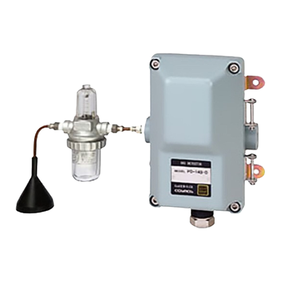
Extractive type Gas Detector
Model PD-14
Instruction Manual
Keep this instruction manual where it is readily accessible.
Thoroughly read this instruction manual before using the equipment so it can be used safely
and correctly.
This manual provides information concerning standard specifications. If the specifications of
your model are nonstandard, refer to the delivery specifications.
Instruction Manual No.
GAE-044
August 2012
Advertisement
Table of Contents

Related Manuals for New Cosmos Electric PD-14


Summary of Contents for New Cosmos Electric PD-14
- Page 1 Extractive type Gas Detector Model PD-14 Instruction Manual Keep this instruction manual where it is readily accessible. Thoroughly read this instruction manual before using the equipment so it can be used safely and correctly. This manual provides information concerning standard specifications. If the specifications of your model are nonstandard, refer to the delivery specifications.
- Page 2 Part Names and Functions Replacement of Sensor Unit See page 4 to 6. See page 20 to 21. Wiring and Connecting Maintenance Check and Methods Operation Methods See page 11 to 14. See page 16 to 23. CVVS cable Indicator alarm unit Shield Ground...
-
Page 3: Table Of Contents
Table of Contents Introduction ..........................1 Precautions ..........................2 Contents of Package......................... 3 External Dimensions and Part Names..................4 4-1. Main Unit ........................4 4-2. Terminal Block ........................ 5 4-3. Flow Diagram ......................... 6 Installation ..........................7 5-1. Installation Method ......................7 5-2. -
Page 4: Introduction
1. Introduction Thank you for purchasing PD-14 Extractive type Gas Detector. In order to ensure the correct and safe operation of this product, be sure to read this manual before use. This product detects various types of gas including combustible gas and detects gas leakage at an early stage in industrial facilities (e.g., gas manufacturing facilities, chemical... -
Page 5: Precautions
2. Precautions Read this manual completely and be sure you understand the information provided herein ● before attempting to use the product. Abide by all applicable laws and regulations when using this product. ● WARNING Be sure to ground the product to prevent electric shocks. If there is a gas leak alarm, take the necessary measures in accordance with your company’s regulations. -
Page 6: Contents Of Package
3. Contents of Package The product is provided with the following items. Make sure that none of these items is ● missing. Although the product is packed and shipped with the utmost care, contact your New Cosmos ● representative if there should be any damage or missing items. Accessories Optional items Detector head... -
Page 7: External Dimensions And Part Names
4. External Dimensions and Part Names 4-1. Main Unit Number Name Description Casing cover Casing Sensor unit Incorporates a gas sensor. Pump unit Draws sample gas and exhaust it. Ground terminal Used when grounding the frame. Cable gland Used for securing the cable. (Size: G 3/4) Gas inlet Inlet for sampled gas. -
Page 8: Terminal Block
4-2. Terminal Block Terminal Block Pump power Gas detector Sensor connector Terminal block 1 2 3 4 5 6 Ground terminal O-ring Number Name Description 24V(+) Pump power supply PA(+) Pump power supply PB(-) Gas detector Ground terminal Used to ground the frame. -
Page 9: Flow Diagram
4-3. Flow Diagram Sensor Pump Flow checker FC-32 Terminal block Gas detector Pump power supply Main components and functions 1) Sensor : Converts gas concentration detected to an electrical signal. One from the catalytic combustion sensor, hot-wire semiconductor sensor or thermal conductivity sensor is on the detector. -
Page 10: Installation
5. Installation 5-1. Installation Method CAUTION Be careful not to damage the gas detector when installing. Otherwise, the explosion-poof performance of the gas detector will be lost. Use appropriate piping material considering type of gas to be detected. Maximum length of the piping should be less than 20m. pay attention that the response time of the detector shall be delayed when the length of the piping is longer du to transport time of sampled gas. - Page 11 1) Locate the tip of gas sampling pipe to be appropriate for the specific gravity of gas to be detected. It must also be placed in a location where the target gases are likely to accumulate. Installing height Type of gas Installing height Remarks A maximum of 10cm above...
- Page 12 3) Mount the main unit to the wall with M6 screws. It is necessary to open the casing cover at the time of wiring and replacing sensor. Install the gas detector in places where the cover opening angle can be more than 90 degrees. Be sure to install the protective cover (optional) when mounting the main unit outdoors.
-
Page 13: Mounting Of Optional Items
5-2. Mounting of Optional Items Protective cover ● Protective cover PW-41 Flow checker FC-32 M3 screw Gas collector Sampling pipe PF-N3 CAUTION Secure the casing cover with M3 screws if strong winds are expected. Auto drain AD-40 ● Auto drain AD-40... -
Page 14: Wiring Method
6. Wiring Method 6-1. Wiring work Be sure to provide explosion-proof wiring if the product is used in hazardous places. ● CAUTION All necessary work for the product including wiring and installation should be carried out by suitably trained personnel in accordance with applicable code of practice. Cable work ●... -
Page 15: Wiring And Connection
6-2. Wiring and Connection WARNING Before opening the casing cover of the gas detector, be sure to turn off the product and all devices (e.g. indicator unit and signal converter) connected to the product. If the power is turned ON, the power supply may become a source of ignition. Be sure to ground the product to prevent electric shocks. - Page 16 MEMO If the main unit is grounded on the power supply side, do not connect a shielded cable to the ground terminal in the gas detector, or otherwise two-point grounding will result. CVVS cable PE-14 Indicator Shield Ground terminal Ground terminal Not grounded Grounded on power supply...
- Page 17 Typical connection procedure Prepare power supply which can provide 24V DC. (Do not turn on the power supply before wiring the main unit.) Loosen the hexagon socket bolts on the four corners of the main unit with provided hexagon wrench of nominal diameter 6 mm to open the casing cover. Remove the screws on the cable ground and run cables through it.
-
Page 18: Precautions Before Use
7. Precautions before Use CAUTION Before turning ON any devices (e.g., indicator unit, signal converter) connected to the product, double check all the connections are correct. Make sure that the gas detector and indicator unit or signal converter, in particular, are properly connected. In Case of Gas Leakage ●... -
Page 19: Maintenance Check And Operation Method
8. Maintenance Check and Operation Method 8-1. Daily Inspection and Periodical Inspection Daily inspections are conduced by the user, while periodical inspections are conducted by ● your local representative. Frequency Checking item Contents of inspection • Corrosion of the gas detector. •... -
Page 20: Preparing Calibration Gas
Frequency Checking item Contents of inspection • Apply inspection gas to the gas detector and check the alarm activation. • Remove the upper cup of flow checker FC-32 and connect to a gas bag as below, and apply inspection gas. Gas bag Upper cup More than... -
Page 21: Preparing Calibration Gas
8-2. Preparing Calibration Gas ● Calibration gas is used for actual gas inspection. ● The following example shows how to prepare a standard gas of 0.72vol% (40%LEL) isobutane. With standard gas cylinder Fill a gas bag with standard gas as shown the figure below. ●... - Page 22 Without standard gas cylinder Use Gas Calibration Kit (optional item) and pure gas cylinder (isobutane 99 vol% or more). ● Dilute isobutane with air to produce calibration gas of 0.72 vol% (40%LEL). This calibration gas can be used to check the alarm function. Check the concentration MEMO by Gas Detector XP-3110 or a similar device before using for calibration.
-
Page 23: Replacement Of Sensor Unit
8-3. Replacement of Sensor Unit WARNING Be sure to turn OFF the indicator unit or signal converter before replacing a sensor unit. The electric power may become a source of ignition. Do not damage the surface of detector when sliding the sensor unit, or the explosion proof performance may be adversely affected. - Page 24 Sensor unit fixing screws (6, 7) Sensor unit fixing plate (6. 7) Pump unit (5, 10) Sensor connector (3, 8,. 9) Sensor unit (6, 7) Movement of Sensor box (7) pump unit (5, 10) Set the groove on the sensor unit to the dent on the sensor box and fix Pump unit fixing screws (4, 10) the sensor unit.
-
Page 25: Replacement Of Pump Unit
8-4. Replacement of Pump Unit WARNING Be sure to turn OFF the indicator unit or signal converter before replacing a sensor unit. The electric power may become a source of ignition. Do not damage the surface of detector when sliding the sensor unit, or the explosion proof performance may be adversely affected. -
Page 26: Replacement Of Filter For Flow Checker (Fc-32)
8-5. Replacement of Filter for Flow Checker (FC-32) If the flow rate returns to normal value (more than 0.7L/min) by removing the bottom filter ● of flow checker FC-32, the filter is possibly being clogged. Please replace the filter when necessary according to the procedure described below. -
Page 27: Specifications
9. Specifications PD-14A: Hot wire semiconductor Corresponding PD-14B: Catalytic combustion sensor type PD-14C: Thermal conductivity Sampling method Extractive Target gas Depends on the specifications Detection range Depends on the specifications Suction flow rate More than 0.7 L/min Explosion-proof Ex d II B+H2 T4 (Japan) class Degree of protection IP 65... -
Page 28: Warranty
10. Warranty New Cosmos Electric Company Limited (New Cosmos) offers the following as the sole and exclusive limited warranty available to the customer. This warranty is in lieu of, and customer waives, all other warranties of any kind or nature, expressed or implied, including without limitation, any warranty for merchantability or fitness for a particular purpose. -
Page 29: Life Expectancy
11. Life Expectancy The design period longevity under a general environmental condition of this container is about five years from purchase. The design life expectancy after the guaranteed term passes is not the one to guarantee this. It is only a guide when a prescribed gas is proofread and it uses it. -
Page 30: Detection Principle
12. Detection Principle 12-1. Catalytic Combustion Catalytic combustion occurs on the catalyst even at a gas concentration below the lower limit of combustion due to the operation of the catalyst applied to the platinum coil. The electrical resistance of the platinum coil increases because of the rise in the temperature at this point. This difference is extracted as deviation voltage in the bridge circuit. -
Page 31: Glossary
13. Glossary Indicator / Alarm unit: A unit that receives signals from the gas detector and indicates gas concentration and alarms. Detector: A unit that detects gas concentration and converts it to electric signals. Backup power source device: A device that supplies power to the gas detector, indicator / alarm unit in order to maintain its performance during a power failure. - Page 32 Date Revisions GAE-044 August 2012 Additional copies of this Instruction Manual are available. Contact the following address for ordering information. Distributor: Manufacturer: New Cosmos Electric Co., Ltd. 2-5-4 Mitsuya-naka Yodogawa-ku Osaka 532-0036, Japan Phone 81-6-6309-1505 Fax 81-6-6308-0371 Email e-info@new-cosmos.co.jp http://www.new-cosmos.co.jp...
Need help?
Do you have a question about the PD-14 and is the answer not in the manual?
Questions and answers