Table of Contents
Advertisement
Quick Links
Diffusion type Gas Detector
Model KD-14
Instruction Manual
Keep this instruction manual where it is readily accessible.
Thoroughly read this instruction manual before using the equipment so it can be used safely and
correctly.
This manual provides information concerning standard specifications. If the specifications of
your model are nonstandard, refer to the delivery specifications.
Instruction Manual No.
GAE-043
August 2012
Advertisement
Table of Contents

Related Manuals for New Cosmos Electric KD-14


Summary of Contents for New Cosmos Electric KD-14
- Page 1 Diffusion type Gas Detector Model KD-14 Instruction Manual Keep this instruction manual where it is readily accessible. Thoroughly read this instruction manual before using the equipment so it can be used safely and correctly. This manual provides information concerning standard specifications. If the specifications of your model are nonstandard, refer to the delivery specifications.
- Page 2 • • • • Part Names and Functions • • • • Replacement of Sensor Unit See pages 4 to 5. See pages 18 to 19. • • • • Wiring and Connecting • • • • Maintenance Check and Methods Operation Methods See pages 11 to 13.
-
Page 3: Table Of Contents
Table of Contents 1. Introduction........................... 1 2. Precautions........................... 2 3. Contents of Package ........................3 4. External Dimensions and Nomenclature..................4 4-1. Main Unit..........................4 4-2. Terminal Block ........................5 5. Installation ............................ 6 5-1. Installation Method ........................ 6 5-2. Examples of Installation Positions..................9 5-3. -
Page 4: Introduction
1. Introduction • Thank you for purchasing the KD-14 Diffusion type Gas Detector. • In order to ensure the correct and safe operation of this product, be sure to read this manual before use. • This product detects various types of gas including combustible gas. The product detects gas leakage at an early stage in industrial facilities, such as gas production plants and depots, chemical plants, paint factories, and power plants. -
Page 5: Precautions
2. Precautions • Read this manual completely and be sure you understand the information provided herein before attempting to use the product. • Abide by all applicable laws and regulations when using this product. WARNING Be sure to ground the product to prevent electric shocks. If there is a gas leak alarm, take the necessary measures in accordance with your company's regulations. -
Page 6: Contents Of Package
Note: 1. The standard product incorporates a built-in pressure-proof packing (12.5-mm dia.), washer (12-mm dia.), and B-clamp. 2. A hexagon wrench and Instruction Manual are provided for each order. 3. The optional items are for use only by the KD-14. -
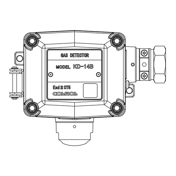
Page 7: External Dimensions And Nomenclature
4. External Dimensions and Nomenclature 4-1. Main Unit Number Name Description Casing cover Casing Sensor unit Incorporates a gas sensor. Sensor guard Protects the sensor unit. Ground terminal Used when grounding the frame. Cable gland Used to secure the cable. Compatible screw: G3/4. Bolt with hexagon Used for securing the cable gland. -
Page 8: Terminal Block
4-2. Terminal Block Gas Detector Ground terminal Terminal A A A A B B B B C C C C D D D D Sensor O-ring connector Number Description Gas detectors Ground terminal Use to ground the frame. -
Page 9: Installation
5. Installation 5-1. Installation Method CAUTION Be careful not to damage the gas detector when installing it. Otherwise, the explosion-proof performance of the gas detector will be lost. Do not install the product in the following places. - Places where the ambient temperature exceeds the operating temperature range (−10°C to 50°C). - Page 10 • Mount the main unit to the wall with the M5 screws that are provided with the product. Be sure to install the protective cover (optional) when mounting the main unit outdoors. Mount the main unit with a 2B pole mounting bracket (optional) when mounting the main unit to a 2B pole. Refer to 5-3 Mounting of Options for details of optional products.
- Page 11 • When installing the diffusion type gas detector to the ceiling or high location, consider to secure the work space underneath the detector for inspection and maintenance. Also, in case of installing the detector at higher location than 3 meters, the sampling pipe should be laid down to the ceiling.
-
Page 12: Examples Of Installation Positions
5-2. Examples of Installation Positions • Install the product in places where gas easily accumulates. Places where gas easily accumulates. Gas Detector Roof fan (Exhaust port) Entrances and windows (Suction and exhaust ports) Gas detector Entrance mounting (Suction port) position Plan view Side view Example of Installation Position... -
Page 13: Mounting Of Optional Items
5-3. Mounting of Optional Items ・Protective Cover (169) (90) (90) M3 screw (169) M3 screw (169) (169) Horizontal Type (KW-41) Vertical Type (KW-42) CAUTION Secure the casing cover with M3 screws if strong winds are expected. ・2B Pole Mounting Bracket... -
Page 14: Wiring Method
6. Wiring Method 6-1. Wiring Work ・ Be sure to provide explosion-proof wiring if the product is to be used in hazardous places. CAUTION Licensed members should implement all necessary work for the product including wiring and installation in accordance with all applicable laws, regulations and standard. -
Page 15: Wiring And Connection
6-2. Wiring and Connection WARNING Before opening the casing cover of the gas detector, be sure to turn off the product and all devices (e.g., indicator unit and signal converter) connected to the product. If the power is turned ON, the power supply may become a source of ignition. Be sure to ground the product to prevent electric shocks. - Page 16 MEMO ● If the main unit is grounded on the power supply side, do not connect a shielded cable to the ground terminal (E) in the gas detector, or otherwise two-point grounding will result. Connection example with power supply side grounded CVVS cable Indicator Ground terminal on...
-
Page 17: Precautions Before Use
7. Precautions before Use CAUTION Before turning ON any of the devices (e.g., indicator unit, signal converter) connected to the product, recheck that all of the connections are correct. Make sure that the gas detector and indicator unit or signal converter, in particular, are connected properly. In Case of Gas Leakage DANGER Without panicking, check that there is no fire around the product. -
Page 18: Maintenance Check And Operation Method
8. Maintenance Check and Operation Method 8-1. Daily Inspection and Periodical Inspection Daily inspections are conducted by the user, while periodical inspections are conducted by your local representative. Frequency Checking item Contents of inspection • Clogging of flame arrester. • Corrosion of flame arrester. At least once Visual check •... -
Page 19: Preparing Calibration Gas
8-2. Preparing Calibration Gas • Calibration gas is used for actual gas inspection. • The following example shows how to prepare a standard gas of 0.72vol% (40%LEL) isobutane. With a standard gas cylinder Fill a gas bag with standard gas as shown the figure below. ●... - Page 20 Without standard gas cylinder Use Gas Calibration Kit (optional item) and pure gas cylinder (isobutane 99 vol% or more). ● Dilute isobutane with air to produce calibration gas of 0.72 vol% (40%LEL). Memo The calibration gas can be used to check the alarm function. Check the concentration using Gas Detector XP-3110 or a similar device before using the gas for calibration.
-
Page 21: Replacement Of Sensor Unit
8-3. Replacement of Sensor Unit WARNING • Be sure to turn OFF the indicator unit or signal converter before replacing a sensor unit. Otherwise, they may become a source of ignition. • Do not damage the surface of detector when sliding the sensor unit, or the explosion proof performance may be adversely affected. - Page 22 Sensor unit Sensor replacement jig Sensor guard Turn OFF the power supply connected to the product. Loosen the bolt with a hexagon socket on each of the four corners of the main unit with the provided hexagon wrench with a nominal diameter of 4 mm, and open the casing cover of the main unit.
-
Page 23: Specifications
9. Specifications Hot wire semiconductor type (KD-14A) Corresponding Catalytic combustion type (KD-14B) sensor type Thermal conductivity type (KD-14C) Sampling method Diffusion type Detection gas Depends on the specifications Detection range Depends on the specifications Explosion-proof Exd II CT5 (Japan) performance Degree of IP65 protection... -
Page 24: Warranty
10. Warranty New Cosmos Electric Company Limited (New Cosmos) offers the following as the sole and exclusive limited warranty available to the customer. This warranty is in lieu of, and customer waives, all other warranties of any kind or nature, expressed or implied, including without limitation, any warranty for merchantability or fitness for a particular purpose. -
Page 25: Life Expectancy
11. Life Expectancy The design period longevity under a general environmental condition of this container is about five years from purchase. The design life expectancy after the guaranteed term passes is not the one to guarantee this. It is only a guide when a prescribed gas is proofread and it uses it. It might be impossible to use between the proofreading and the proofreading schedule for the next term. -
Page 26: Detection Principle
12. Detection Principle 12-1. Catalytic Combustion Catalytic combustion occurs on the catalyst even at a gas concentration below the lower limit of combustion due to the operation of the catalyst applied to the platinum coil. The electrical resistance of the platinum coil increases because of the rise in the temperature at this point. This difference is extracted as deviation voltage in the bridge circuit. -
Page 27: Glossary
13. Glossary Indicator / Alarm unit: A unit that receives signals from the gas detector and indicates gas concentration and alarms. Detector: A unit that detects gas concentration and converts it to electric signals. Backup power source device: A device that supplies power to the gas detector, indicator / alarm unit in order to maintain its performance during a power failure. - Page 28 Date Revisions GAE-043 August 2012 Additional copies of this Instruction Manual are available. Contact the following address for ordering information. Distributor: Manufacturer: New Cosmos Electric Co., Ltd. 2-5-4 Mitsuya-naka Yodogawa-ku Osaka 532-0036, Japan Phone 81-6-6309-1505 Fax 81-6-6308-0371 Email e-info@new-cosmos.co.jp http://www.new-cosmos.co.jp...
Need help?
Do you have a question about the KD-14 and is the answer not in the manual?
Questions and answers