Table of Contents
Advertisement
Quick Links
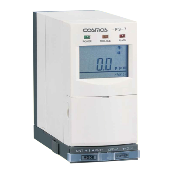
PS-7 Series
Extractive Pump Gas Detector
(Detachable Sensor and Sampling Units)
Instruction Manual
Keep this manual for easy reference.
Carefully read this manual prior to use.
This manual describes the standard model. If your unit has end-user-specific
options, this manual will be superseded by your delivery specifications.
Instruction Manual No.
GAE-018-02
Aug 2020
Advertisement
Table of Contents

Related Manuals for New Cosmos Electric PS-7 Series


Summary of Contents for New Cosmos Electric PS-7 Series
- Page 1 PS-7 Series Extractive Pump Gas Detector (Detachable Sensor and Sampling Units) Instruction Manual Keep this manual for easy reference. Carefully read this manual prior to use. This manual describes the standard model. If your unit has end-user-specific options, this manual will be superseded by your delivery specifications.
- Page 2 Unit Dimensions and Sensor Unit Components Installation/Replacement 5. ―Unit Dimensions and Components‖ 9-2. ―Sensor Unit Installation /Replacement‖ on pages 34 to 36 on pages 5 to 9 Operation Base Unit installation/Wiring 7-1. ―Operation‖ on pages 15 to 24 6-1. ―Installation and Wiring‖ on pages 11 and 12 Normal operation on page 24 Cable entry Gas outlet...
-
Page 3: Table Of Contents
Table of Contents Introduction ..............................1 General Precautions ............................. 2 Package Contents ............................3 Block Diagram ............................... 4 Unit Dimensions and Components ....................... 5 5-1. Exterior Appearance ..........................5 5-2. Main Unit ..............................6 5-3. Base Unit ..............................7 5-4. Operation Buttons ............................8 5-5. -
Page 4: Introduction
PS-7 series gas detectors are divided into the following six models according to the sensor unit type and with/without a pyrolyzer. For sensor selection, please contact New Cosmos or its authorized representative. -
Page 5: General Precautions
2. General Precautions To ensure safe operation, follow the precautions given below. Only use this product in accordance with the applicable laws and regulations. Wiring and installation should only be performed by a qualified electrician with knowledge of wiring/installation procedures. -
Page 6: Package Contents
3. Package Contents The following items are included in a standard package. If any items are missing or damaged, please contact New Cosmos or its authorized representative for replacement. Standard contents Item Quantity Gas detector (PS-7) Half union (R1/4-ø6mm or R1/4-ø1/4 in. selectable) Replacement filter elements (FE-1, 12 pcs.) for MF-50 filter unit Replacement fuse (125 V, 1.0 A), normal blow or time lag Mounting screws (M48) -
Page 7: Block Diagram
4. Block Diagram MF-50 filter unit Sampling unit Sensor Pump Gas out Gas in Rc 1/4 Rc 1/4 Flow sensor Gas in Controller Rc 1/4 Power 24VDC board Analog output 4–20mADC Earth terminal Maintennce Jack stage alarm Gas alarm contact output (NO) Membrane stage alarm SW panel... -
Page 8: Unit Dimensions And Components
5. Unit Dimensions and Components 5-1. Exterior Appearance (Dimensions are in mm) Item Component Description/Function Main unit Includes a display, a pump and a sensor Thread cables through the cable entry hole at the bottom of the Base unit base unit Incorporates a filter element (FE-1) that prevents dust from entering Filter unit (MF-50) the gas inlet and the sensor... -
Page 9: Main Unit
5-2. Main Unit (Dimensions are in mm) Item Component Description/Function When lit, it indicates that the unit is in normal operation Green POWER LED mode (gas-monitoring mode) Amber TROUBLE LED Flashing indicates the presence of an internal failure Red ALARM LED Flashing indicates the presence of a gas alarm Displays alarm notification, numeric gas concentration value, gas concentration on a bar graph, trouble... -
Page 10: Base Unit
5-3. Base Unit (Dimensions are in mm) Item Component Description/Function Fuse Internal circuit protection in the event of a current surge Base unit’s power switch Turns the base unit on/off Mounting hole (2 places) Dia. 5.5 mm Terminal block (2 places) Used for external wiring Turns the main unit on/off Main unit’s power switch... -
Page 11: Operation Buttons
5-4. Operation Buttons Opening front cover Pull and slide down the front cover to access the operation buttons and TEST switch. Front cover Slide down Pull open Panel Item Component Description/Function marking SPAN button Performs span adjustment. For O sensor unit SPAN (Span adj. -
Page 12: Lcd Indicator Icons
5-5. LCD Indicator Icons Item Icon/Display Description/Function Displays gas concentration and the unit of measurement Numeric display (e.g., %LEL, ppb, ppm) FLOW Lit when the flow rate is low. Linked with item 6 ALARM1 ALARM2 Lit when the 1st or 2nd stage gas alarm is on Lit when there is a sensor fault (e.g., broken wire) or an SENS. -
Page 13: Installation And Wiring
6. Installation and Wiring DANGER This product is not explosion-proof and thus should not be installed in a hazardous area. WARNING For detection of highly adsorptive gas (e.g., HF and F ), remove the filter element (FE-1) from the filter unit (MF-50). Correct detection is not possible if the filter element is present. Refer to 9-1. -
Page 14: Unit Installation Procedure
CAUTION Install the gas detector in a place free from impact and vibration. Do not install in the vicinity of equipment that can generate high frequencies or a magnetic field. Do not use a gas collector in a confined space (e.g., inside a duct). ... - Page 15 6. To install the main unit, pull forward and hold both the latches of the base unit. Connect the main unit by sliding it onto the rails of the base unit. (2) Align with the rail and slide Rail (1) Pull forward and hold the latches at both sides (unlock position) 7.
-
Page 16: Tube Fitting Connection Procedure
6-2. Tube Fitting Connection Procedure Install the half unions (provided) into the gas inlet and outlet. CAUTION Over-tightening the filter unit inlet may cause the gas inlet to break. When connecting the half union to the filter unit inlet, secure the filter unit inlet with one adjustable wrench or spanner, etc. -
Page 17: Wiring Procedure
6-3. Wiring Procedure Terminal Marking Polarity Function block + Power input (24 VDC) - + Gas concentration output - (4–20 mADC) Earth terminal stage gas alarm contact output (Dry NO contact) Max. load: 125 VAC or 30 VDC 0. 5 A (resistive load) stage gas alarm contact output (Dry NO contact) Max. -
Page 18: Operation
7. Operation 7-1. Operation Procedure Operation Flow The corresponding numbered steps are given for items 1–12 on the following pages. Initial startup Check the power 1. Is power voltage source. Check the wiring to the 24 VDC±10%? terminal blocks. 2. - Page 19 WARNING When using the 24 VDC power supply, ensure that the power is 24 VDC 10%. Check that the target gas type and full scale value are correct before using a new sensor unit. Also, check that the sensor unit expiration date has not been reached. ...
- Page 20 COMM-less models (2) For COMM-less models a. Connect the loop checker (LC-7) to the base unit. b. Set the MNT2 analog output level to 4.0 mA or 17.4 mA depending on the sensor unit type using the 17.4 mA/4.0mA switch. Sensor unit type MNT2 analog level CDS-7...
- Page 21 (3) For models other than COMM-less models Toxic gas sensor: CDS-7 Oxygen sensor: COS-7 (FS: 50vol%) Combustible gas sensor: CHS-7 Oxygen sensor: COS-7 (FS: 25vol%) a. Measure the analog output (current) a. Measure the analog output (current) between the ―G‖ and ―H‖ terminals with between the ―G‖...
- Page 22 4. Install the sensor unit into the main unit if not installed yet. For the installation procedure, refer to 9-2. ―Sensor Unit Installation/Replacement.‖ Ensure the main unit’s power switch is in the OFF position before the sensor unit/main unit installation. Install the main unit into the base unit by referring to 6-1. ―Unit Installation Procedure.‖...
- Page 23 8. Check the set values. Note: To change the set values, refer to ―PS-7 gas detector’s operation manual for administrators‖ (a separate document). ■ To view the set values shown in the table below, press the UP/DOWN button. Press the UP/DOWN button to cycle through the items in the sequence as shown in the table. The set value for the selected item is displayed at the bottom-right corner (sub-display).
- Page 24 On sub-display Default set value Description Toxic: CDS-7 A1 10 10% of full scale value A1 ** Combustible: CHS-7 : COS-7 A1 72 72% of full scale value Toxic: CDS-7 A2 20 20% of full scale value A2 ** Combustible: CHS-7 : COS-7 A2 76 76% of full scale value...
- Page 25 10. Check for airtightness. Disconnecting the tube from the gas inlet and fully blocking the inlet with a finger will change the flow-rate icon’s spinning speed from quick to slow. Keep blocking it and check that the flow-rate icon stops spinning and the amber TROUBLE LED starts flashing.
- Page 26 Toxic gas sensor: CDS-7 Oxygen sensor: COS-7 Combustible gas sensor: CHS-7 Press the SPAN button for more than four seconds. The green POWER LED will flash Press the ZERO button for more than two one time, indicating the zero adjustment is seconds.
- Page 27 Normal Trouble alarm stage stage operation (internal failure) gas alarm gas alarm (gas-monitoring) Green lit Amber flash Red flash Red flash FLOW ALARM1 SENS. ALARM1 ALARM2 CONV. Gas alarm contact (ZA1) (closed (closed (open position) (open position) position) position) Gas alarm contact (ZA2) (closed (open position)
-
Page 28: Gas Alarm Operation
7-2. Gas Alarm Operation If the gas concentration exceeds the gas alarm set value, the alarm contacts will activate after the alarm delay time, the red ALARM LED will start flashing, and ALARM1 or ALARM1+ALARM2 will be shown on the LCD. Note: During the alarm delay time, ALARM1 or ALARM1+ALARM2 flash on the LCD, the alarm contact does not activate and the red ALARM LED does not flash. -
Page 29: Trouble Alarm Operation
7-3. Trouble Alarm Operation This unit can detect an internal failure. When an internal failure is detected, a trouble alarm will activate (open collector is normally ON (closed position) and in the event of a trouble alarm it switches to OFF (open position)). - Page 30 CAUTION Oxygen sensor (COS-7): The analog output from this product falls to 0.6 mA or less in the event of a trouble alarm as listed above. When the host system (e.g., control room) is set to the low limit alarm (gas alarm activates when the gas concentration falls to the alarm set value or less) and if the product’s analog output falls to 0.6 mA or less in under a second without a gas alarm, it means that a trouble alarm is present.
-
Page 31: Test Mode
7-4. Test Mode Setting Use the test stick to press the TEST switch to enter the test mode. The TEST switch is pressed to turn the test mode on and off. The test mode will automatically end in 10 minutes. Increase/decrease the analog output value using UP/DOWN button. -
Page 32: Maintenance Mode
7-5. Maintenance Mode Setting The MNT switch has three modes — maintenance mode 1 (MNT1), maintenance mode 2 (MNT2), and normal operation mode (gas-monitoring mode). Set the MNT switch to MNT1 or MNT2 on the base unit’s front, accordingly ―MNT1‖ or ―MNT2‖ will be shown on the LCD. -
Page 33: Maintenance
8. Maintenance This gas detector requires no on-site gas calibration. Each sensor unit is gas-calibrated when shipped. Replace the sensor unit with a new one every 6 months, except for combustible gas sensor units (CHS-7). Routine checks are to be carried out by the user. 6-month and 3-year periodic inspections are to be performed by the user, New Cosmos or its authorized representative. - Page 34 (2) Sampling gas flow rate (flow-rate icon check) Check that the flow-rate icon (at the top-right corner of the LCD) is quickly spinning. Refer to 7-1.9 ―Check the flow rate of the sampled gas.‖ If the flow-rate icon slowly spins or stops, check the filter element for contaminants. If the filter element (FE-1) is dirty, replace it with a new one.
- Page 35 Example of the check/inspection results Model Target gas Full scale value PS-7 250 ppm PS-7 25 ppm Zero-level Alarm set Alarm test Replace output value Flow using the Airtight Filter Replacement Item Location Tubing sampling rate TEST ness element sensor No. Before After unit...
-
Page 36: Consumable Replacement
9. Consumable Replacement This product has been designed such that its consumable parts can be easily replaced by the user. To order, contact New Cosmos or its authorized representative. 9-1. Filter Element Replacement If the filter element (FE-1) is dirty, replace it with a new one by using the following steps: 1. -
Page 37: Sensor Unit Installation/Replacement
9-2. Sensor Unit Installation/Replacement WARNING Check that the target gas type and full scale value are correct before using a sensor unit. Also, check that the sensor expiration date has not been reached. Note: The expiration year/month is not indicated on a combustible gas sensor (CHS-7). CAUTION ... - Page 38 3. Press the top of the rear cover with thumb and pull back the rear cover to separate the rear cover from the main unit Press here then pull back the rear cover. 4. Insert a finger between the main unit and the sensor unit so that the sensor unit slightly tilts forward. Hold the sensor unit by its sides and then pull it out of the main unit.
- Page 39 6. Pull forward and hold the latches at both sides and connect the main unit by sliding it onto the rails of the base unit. (2) Align with the rail and slide on Rail (1) Pull forward and hold the latches at both sides (unlock position) 7.
-
Page 40: Sampling Unit Replacement
9-3. Sampling Unit Replacement CAUTION Turn off the gas detector before sampling unit replacement. Setting the main unit’s power switch to the OFF position will generate a trouble alarm output (open collector is opened (OFF)). If the trouble alarm output is used to operate the interlocks, etc. of the external devices, release the interlocks, etc. - Page 41 4. Connect the two connectors. Mate the sampling unit and front panel. Insert the sensor unit and install the rear cover. Front panel Rear cover Ensure that cables are not caught WARNING If the sensor unit is not completely inserted, an airtight seal will not be created, and correct gas detection will not be possible.
-
Page 42: Activated Chacoal Filter Installation/Replacement
9-4. Activated Chacoal Filter Installation/Replacement WARNING Only use an activated charcoal filter when the target gas is NF CAUTION Replace the activated charcoal filter’s inner sleeve (KF-6S-Y1) at the time of replacing the sensor unit. Turn off the gas detector before filter installation/replacement. Setting the main unit’s power switch to the OFF position will generate a trouble alarm output (open collector is opened (OFF)). -
Page 43: Troubleshooting
10. Troubleshooting Before requesting for repair, please refer to the table below. If the detector does not return to normal operation after performing the corresponding steps in the table, or if your issue is not found in the table, consult New Cosmos or its authorized representative. - Page 44 Problem Probable cause Steps Reference section mode. Set the MNT switch to MNT switch is set to the center position for 7-5. Maintenance MNT1 or MNT2 normal operation Mode No alarm contact mode. output Check and rewire. 6-3. Wiring Incorrect wiring Securely connect the Procedure wires to the terminals.
-
Page 45: Specifications
11. Specifications Model PS-7 series Detection principle Electrochemical, hot-wire semiconductor, or galvanic cell Sampling method Extractive pump (500 mL/min. auto-controlled) Sampling tube PTFE, outside and inside dia.: 6mm and 4mm (or 1/4 in. and 11/64 in.) respectively Tube length: 20 m... - Page 46 24 VDC 10% Power supply Sensor unit CDS-7 COS-7 CHS-7 CDS-7+CDP-7 Power Typical 2.2 W 2.7 W 2.9 W 5.0 W consumption Max. 4.2 W 4.2 W 5.0 W 7.8 W Dimensions W62 mm × H124 mm × D143 mm (excluding protrusions) Mass Approx.
-
Page 47: Warranty
12. Warranty The warranty period is one (1) year from the date of purchase. You are entitled to the limited warranty, if the product malfunctions due to a manufacturing defect during normal use in accordance with the instruction manual, specifications and labels. 1. -
Page 48: Electrochemical Sensor
Detection Principle 13-1. Electrochemical Sensor This sensor consists of three electrodes and an electrolyte, and the method adopted here is to produce electrolytic oxidation with a potentiostat circuit while keeping the working electrode at a constant potential against the reference electrode. Measuring the current generated here allows determining the concentration of the gas (e.g., H S, CO). -
Page 49: Glossary
14. Glossary Term Definition Device used to detect the presence of a target gas and to give Gas detector its concentration in the form of an electrical signal. Target gas Specific gas to be detected, concentration displayed, and used to trigger alarms. A gas concentration value that is set on a gas detector for Alarm set value alarm activation. - Page 50 Initial issue GAE-018-01 June 2009 GAE-018-02 Aug 2020 Additional copies of this instruction manual may be purchased. Contact New Cosmos or its authorized representative for ordering. Authorized representative: Manufacturer: NEW COSMOS ELECTRIC CO., LTD. 2-5-4 Mitsuya-naka, Yodogawa-ku, Osaka 532-0036, Japan www.newcosmos-global.com...
Need help?
Do you have a question about the PS-7 Series and is the answer not in the manual?
Questions and answers