Table of Contents
Advertisement
Quick Links
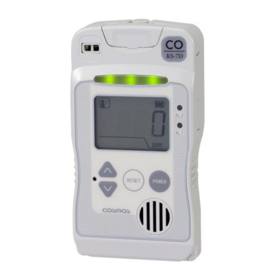
Carbon Monoxide Detector
KS-7D
Instruction Manual
Keep this manual for easy reference.
Carefully read this manual prior to use.
This manual describes the standard model. If your unit has end-user-specific
options, this manual will be superseded by your delivery specifications.
Instruction Manual No.
GAE-053-03
June 2019
Advertisement
Table of Contents

Related Manuals for New Cosmos Electric KS-7D


Summary of Contents for New Cosmos Electric KS-7D
- Page 1 Carbon Monoxide Detector KS-7D Instruction Manual Keep this manual for easy reference. Carefully read this manual prior to use. This manual describes the standard model. If your unit has end-user-specific options, this manual will be superseded by your delivery specifications.
-
Page 2: Table Of Contents
Table of Contents 1. Introduction ..........................1 2. General Precautions ........................2 3. Package Contents ........................3 4. Unit Dimensions and Components .................... 4 4-1. Outer Appearance ......................4 4-2. Inner Components ......................5 5. Installation ..........................6 6. Wiring ............................9 6-1. -
Page 3: Introduction
1. Introduction Thank you for purchasing the New Cosmos KS-7D carbon monoxide detector. To ensure safe and reliable operation, please read this instruction manual prior to use. This unit detects the toxic and combustible gas, carbon monoxide. The unit is intended for use in a non-hazardous indoor area, e.g. -
Page 4: General Precautions
2. General Precautions Carefully read this manual prior to use. Follow the precautions below to ensure safe operation. Only use this product in accordance with applicable laws and regulations. Only a qualified electrician with knowledge of wiring and installation procedures should perform wiring and installation. -
Page 5: Package Contents
The following items are included in a standard package. If any items are missing or damaged, please contact New Cosmos or its authorized representative for replacement. Item Description CO detector (KS-7D) Mounting screw M5x12 with spring washer (Wall mounting) Cable tie... -
Page 6: Unit Dimensions And Components
4. Unit Dimensions and Components 4-1. Outer Appearance Dimensions are in mm. Item Component Description/Function Slide up and lift the cover to access to the main power switch and to Cover wire external cables. This cover is normally closed. Houses one mounting screw, and two fastening screws that attach the Screw cover cover to the unit. -
Page 7: Inner Components
Item Component Description/Function Speaker opening Opening for audio. Make a cutout (cable entry) with a nipper to connect external cables to Cable entry (3 places) the terminals. Maintenance button Recessed button used for making settings. 4-2. Inner Components Item Component Description/Function Slide up and lift the cover to access to the main power switch and Cover... -
Page 8: Installation
5. Installation WARNING This product is not explosion-proof equipment and should not be installed in a hazardous area. CAUTION ▪ Avoid strong mechanical shock, impact or vibration to the detector by dropping or bumping. Failure to do so may impair the performance of the detector. ▪... - Page 9 Clearance for cover to slide Mounting hole Sensor Mounting hole Cable entry Dimensions are in mm. Wall-mount the detector using two M5 mounting screws (pitch: 134) according to the following procedure. Open the screw cover. Loosely install the mounting screw (top). Loosen the two fastening screws.
- Page 10 Slide the cover up (cover is open). Firmly tighten the mounting screw (bottom) to secure the detector to the wall. Slide the cover down (cover is closed). 7. Slide the cover down 5. Slide the cover up 6. Tighten the mounting screw (bottom) While pressing down the cover toward the case, tighten the mounting screw (top).
-
Page 11: Wiring
6. Wiring WARNING ▪ Remove any power source during wiring work to prevent electric shocks. ▪ After wiring is completed, close the detector’s cover to prevent electric shocks. CAUTION ▪ New Cosmos is not responsible for the cost or any damage resulting from controlling external equipment (e.g. -
Page 12: Pin Terminal/Insulated Sleeve Installation
6-1. Pin Terminal/Insulated Sleeve Installation Recommended parts/tools Part Model (Manufacturer) Description Shielded cable (with 0.5-1.25mm wires) Electric cable Outer diameter: 10.5mm or less (Included in package) Pin terminal TC1.25-16 (Nichifu) Used for 0.25- 1.65mm twisted wire Insulating sleeve VC1.25 (Nichifu) (Included in package) Crimping tool NH1 (Nichifu) -
Page 13: Wire Connection/Disconnection To/From Terminal Block
6-2. Wire Connection/Disconnection to/from Terminal Block 6-2-1. Power Terminal Block (Disconnection) (Connection) Insert each pin terminal to its While pressing the release button with a corresponding slot on the terminal block. precision screwdriver (recommended tip thickness: 2.6 mm), lift the pin terminal. 6-2-2. -
Page 14: Operation
7. Operation 7-1. Precautions before Use WARNING ▪ Prior to operation, confirm that the power supply is 24V DC +/-10% CAUTION ▪ Before turning on the unit, check that all wiring is correct. Refer to 6. “Wiring” or delivery specifications if provided. ▪... - Page 15 3) Follow steps 7, 8, and 10 of 5. “Installation”, close the cover and tighten the screws. 7. Slide the cover down (cover is closed) Status indicator 8. While pressing down the cover toward the case, 10. secure the screw cover to the case with the two fastening screws.
-
Page 16: Lcd Operation
7-3. LCD Operation 7-3-1. LCD Item Icon/Display Description/Function Audio alarm icon Always present. AL1 icon stage alarm notification. AL2 icon stage alarm notification. Sensor replacement icon Sensor needs to be replaced. Backup battery icon Unit is operating on the backup battery. Battery level of the backup battery used during power Backup battery level indicator outage. -
Page 17: Full Scale And Alarm Set Values Display
7-3-3. Full Scale and Alarm Set Values Display ▪ Press the RESET button (one beep) to display the “full scale concentration”, “1st stage alarm set value”, and “2nd stage alarm set value” in sequence. Full scale: 400ppm stage alarm set value: 50ppm stage alarm set value: 150ppm 7-3-4. -
Page 18: User Mode
< 1 stage alarm > ▪ Orange AL1 alarm light flashes and the status indicator sequentially-flashes orange. ▪ Audio alarm beep: Fast, high and low beep tones. ▪ ZA1 alarm relay contact is closed. < 2 stage alarm > ▪ Red AL2 and A1 alarm lights flash and the status indicator sequentially-flashes red. ▪... -
Page 19: Switching Maintenance Mode On/Off [Mode1]
7-4-2. Switching Maintenance Mode On/Off [Mode1] WARNING During the Maintenance mode, the external relay contacts and audio alarm are disabled. Turn off the Maintenance mode during normal operation. 1) Enter the User mode. Press the ▲/▼ button to select “1”. (each press of the button is followed by one beep) “MT”... -
Page 20: Zero Adjustment [Mode 2]
7-4-3. Zero Adjustment [Mode 2] CAUTION ▪ Perform a zero adjustment in clean air that is free from target gas or interfering gases. ▪ Proper gas detection is not possible without a correct zero adjustment 1) Enter the User mode. Press the ▲/▼ button to select “2”. -
Page 21: Alarm Test [Mode 4]
7-4-5. Alarm Test [Mode 4] ▪ When an alarm test is executed, the alarm test value (concentration) will be displayed on the LCD, and corresponding analog output and alarm outputs (external relay contacts, audio alarm, alarm lights) will activate. This will allow the user to test the alarm operation. If the unit is in the Maintenance mode, the external relay contacts and audio NOTE alarm are disabled (alarm lights and analog outputs are active). -
Page 22: Alarm History [Mode 5]
7-4-6. Alarm [Mode 5] History ▪ Up to the 10 most recent alarm events can be displayed (automatically updated). ▪ For each alarm event, the following sequence of information is displayed: peak value (ppm) during the alarm, starting and ending times (year/month/day/time) of the alarm. ▪... -
Page 23: Clock Setting [Mode 6]
6) Press the RESET button (one beep) to display the selected alarm event number “H *”. To display other alarm event, repeat steps 3) to 5). (Ex. H1 is selected) To delete the alarm history, select “INIT” in step 3), then press and hold the maintenance button for 3 seconds. -
Page 24: Maker Mode
7-5. Maker Mode All the items set in the Maker mode (e.g. alarm set value) are password-protected. WARNING ▪ Incorrect settings in the Maker mode may change the detector’s specifications. Never operate in a way other than as described in this instruction manual. ▪... - Page 25 3) Press the maintenance button. (one beep) “4mA” will be displayed. Use a rounded pin (e.g. precision NOTE screwdriver) pressing maintenance button. 4) Press the ▲ button. (one beep) The total operating time will be displayed in hex notation. WARNING Before moving to the next step, “total operating (Ex.
-
Page 26: Alarm Set Value Change
7-5-3. Alarm Set Value Change 1) Refer to 7-5. “Maker Mode” (including the warning), enter the Maker mode. Now “775” is flashing. 2) Press the maintenance button. (one beep) “AL 1” will be displayed and the AL1 alarm light will turn on. 3) Use the ▲/▼... -
Page 27: Maintenance
8. Maintenance Daily checks are carried out by the user, while monthly and annual inspections are performed by the user, New Cosmos or its authorized representative. Important Notice for Maintenance In order to ensure the reliability of the gas detector, it is vital to perform periodic span adjustment on the gas sensor. - Page 28 3) Alarm Test ▪ Check that an alarm activates correctly by referring to 7-4-5. “Alarm Test”. CAUTION ▪ Perform an alarm test in accordance with applicable local laws and regulations. For example, an applicable law in Japan specifies that alarm activation must be checked by performing a circuit check once every month.
-
Page 29: Backup/Clock Battery Replacement
8-2. Backup/Clock Battery Replacement CAUTION ▪ Use a “CR2 lithium battery, cylindrical type” for backup battery. ▪ Use a “CR2032 lithium battery, coin type” for clock battery. 1. Press and hold the POWER button for 3 seconds to turn off the detector. 2. - Page 30 8. Temporarily hang the cover on the top of the case by engaging the cover’s Part E into the case’s Part D. Top of the case Part E Top of the case Part D Engaged 8. Hang 9. Replace backup/clock battery sensor Clock battery Backup battery...
-
Page 31: Troubleshooting
9. Troubleshooting Before requesting repair, please refer to the table below. If the detector does not return to normal operation after performing the corresponding steps in the table, or if your issue is not found in the table, consult New Cosmos or its authorized representative. Problem Probable cause Solution... - Page 32 Problem Probable cause Solution Reference section detector is power cycled. To mute the resumed audio alarm, press the RESET button. ▪ Status indicator Press and hold the flashing between POWER button for 3 green and red. seconds to turn off the ▪...
-
Page 33: Specifications
10. Specifications Detection principle Electrochemical sensor Sampling method Diffusion type Target gas Carbon Monoxide 0-400ppm Detection range (Service range: F.S. value to 1000ppm) Display Four-digit LCD with backlight, resolution 1ppm Alarm set value (AL1/AL2) F.S.400ppm: 50/150ppm Indication accuracy +/- 30% of the alarm set value Alarm is triggered in less than 60 seconds after exposure to test Alarm delay gas (80ppm) -
Page 34: Warranty
11. Warranty The warranty period is one (1) year from the date of purchase. You are entitled to the limited warranty, if the product malfunctions due to a manufacturing defect during normal use in accordance with the instruction manual, specifications and labels. Warranty Scope If the product fails or is found to be damaged due to a manufacturing defect during the warranty period, and used in accordance with the instruction manual and specifications, we will provide a free... -
Page 35: Detection Principle
13. Detection Principle ▪ Electrochemical Sensor Clean Air CO gas is present Working electrode (Pt) Electrolyte (Solid or liquid) passes thru backing layer) Counter electrode (Pt) Sensor consists of a working electrode (noble metal), a counter electrode and an electrolyte. When the CO reaches the working electrode, electrons are generated resulting from the reaction between CO and anions in the electrolyte such as OH (see equation 1). -
Page 36: Glossary
14. Glossary Term Definition Clean air or Standard atmosphere which contains 20.9 to 21.0% oxygen in dry condition or normal air atmosphere without target gas or interference gases. Gas detector Device used to detect the presence of a target gas and to give its concentration in the form of an electrical signal. -
Page 37: Proper Product Disposal At End Of Life
15. Proper Product Disposal At End of Life The Waste Electrical and Electronic Equipment(WEEE)directive(2012/19/EU) is intended to promote recycling of electrical and electronic equipment and their components at end of life. This symbol(crossed-out wheeled bin)indicates separate collection of waste electrical and electronic equipment in the EU countries. This product contain two Lithium batteries. - Page 38 (Blank page)
- Page 39 (Blank page)
- Page 40 GAE-053-02 Oct 2018 GAE-053-03 June 2019 Additional copies of this instruction manual may be purchased. Contact New Cosmos or its authorized representative for ordering. Authorized representative: Manufacturer: NEW COSMOS ELECTRIC CO., LTD. 2-5-4 Mitsuya-naka, Yodogawa-ku, Osaka 532-0036, Japan URL: http://www.newcosmos-global.com...
Need help?
Do you have a question about the KS-7D and is the answer not in the manual?
Questions and answers