New Cosmos Electric KD-12B Instruction Manual
Sil2 capable
Hide thumbs
Also See for KD-12B:
- Instruction manual (40 pages) ,
- Instruction manual (42 pages) ,
- Instruction manual (46 pages)
Table of Contents
Advertisement
Quick Links
Diffusion type Gas Detector
Keep this instruction manual where it is readily accessible.
Thoroughly read this instruction manual before using the equipment so it can be used
safely and correctly.
This manual provides information concerning standard specifications. If the specifications
of your model are nonstandard, refer to the delivery specifications.
New Cosmos Electric Co., Ltd.
Model KD-12B
(SIL2 Capable)
Instruction Manual
Instruction Manual No.
GAE-054-00
July 2014
Advertisement
Table of Contents

Related Manuals for New Cosmos Electric KD-12B


Summary of Contents for New Cosmos Electric KD-12B
- Page 1 Thoroughly read this instruction manual before using the equipment so it can be used safely and correctly. This manual provides information concerning standard specifications. If the specifications of your model are nonstandard, refer to the delivery specifications. New Cosmos Electric Co., Ltd. Instruction Manual No. GAE-054-00 July 2014...
- Page 2 Nomenclature Replacement of Sensor Unit See pages 4 to 6. See pages 31 and 32. Wiring and Connecting Display and Operation in Methods Each Mode See pages 14 to 16. See page 19. 24 V power supply Indicator E.g., External...
-
Page 3: Table Of Contents
Table of Contents Introduction ........................1 Precautions ........................2 Contents of Package ....................3 External Dimensions and Nomenclature ..............4 4-1. Main Unit ........................ 4 4-2. Display and Control Blocks ..................5 4-3. Terminal Block ......................6 Installation ........................7 5-1. -
Page 4: Introduction
1. Introduction Thank you for purchasing the KD-12B (SIL Capable) Diffusion type Gas Detector. In order to ensure the correct and safe operation of this product, be sure to read this manual and the safety manual before use. -
Page 5: Precautions
2. Precautions Read this manual completely and be sure you understand the information provided herein before attempting to use the product. Abide by all applicable laws and regulations when using this product. WARNING Be sure to ground the product to prevent electric shocks. ... -
Page 6: Contents Of Package
3. Contents of Package The product is provided with the following items. Make sure that none of these items is missing. Although the product is packed and shipped with the utmost care, contact your New Cosmos representative if there should be any damage or missing items. Accessories Optional items Detector head... -
Page 7: External Dimensions And Nomenclature
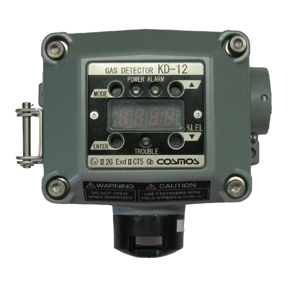
4. External Dimensions and Nomenclature 4-1. Main Unit Number Name Description Casing cover Casing Sensor unit Incorporates a gas sensor. Sensor guard Protects the sensor unit. Ground terminal Used when grounding the frame. State display Indicates the power supply state (green), alarm state (red), and trouble indicator state (yellow). -
Page 8: Display And Control Blocks
4-2. Display and Control Blocks Magnetic switches (Insert the magnetic stick to operate the magnetic switches.) Number Name Description Makes adjustments and settings or cancels the operation of MODE switch the product. ENTER switch Enters settings or completes the control of the product. Makes adjustments and settings or increases set values and UP switch other values. -
Page 9: Terminal Block
4-3. Terminal Block Terminal block 24 V (+) 24V(+) POWER - 4 to 20 mA 4~20mA Signal + Ground Clamp terminal Lever Sensor O-ring connector Number Name Description 24 V (+) Power supply voltage (positive) Power supply voltage(-) and analog signal (negative) common Signal 4- to 20-mA(+) analog signal... -
Page 10: Installation
5. Installation 5-1. Installation Method WARNING The cable entry device and blanking elements shall be of ATEX certified in type of explosion protection flameproof enclosure ‘’d’’, suitable for the condition of use and correctly installed. Use in ATEX hazardous area, ATEX certified cable glands according to EN 60079-0:2012 and EN 60079-1:2007 shall be provided by end-user. - Page 11 CAUTION Be careful not to damage the gas detector when installing it. Otherwise, the explosion-proof performance of the gas detector will be lost. Do not install the product in the following places. - Places where the ambient temperature exceeds the operating temperature range (10C to 50C).
- Page 12 Mount the main unit to the wall with the M5 screws that are provided with the product. Be sure to install the protective cover (optional) when mounting the main unit outdoors. Mount the main unit with a 2B pole mounting bracket (optional) when mounting the main unit to a 2B pole. Refer to 5-3 Mounting of Options for details of optional products.
- Page 13 It is necessary to operate the detector during inspection or maintenance work. Therefore, leave a distance of 50cm or more between the front side of the detector and the object in front of it when installing it. Leave a distance of min. 50cm. ・...
-
Page 14: Examples Of Installation Positions
5-2. Examples of Installation Positions Install the product in places where gas easily accumulates. Places where gas easily accumulates. Gas detector Roof fan Entrances and windows (Exhaust port) (Suction and exhaust ports) Entrance Gas detector (Suction port) mounting position Plan view Side view Example of Installation Position... -
Page 15: Mounting Of Optional Items
5-3. Mounting of Optional items Protective Cover Horizontal Type (KW-41) Vertical Type (KW-42) CAUTION Secure the casing cover with M3 screws if strong winds are expected. 2B Pole Mounting Bracket... -
Page 16: Wiring Method
6. Wiring Method 6-1. Wiring Work Be sure to provide explosion-proof wiring if the product is to be used in hazardous places. WARNING The cable entry device and blanking elements shall be of ATEX certified in type of explosion protection flameproof enclosure ‘’d’’, suitable for the condition of use and correctly installed. -
Page 17: Wiring And Connection
6-2. Wiring and Connection WARNING Before opening the casing cover of the gas detector, be sure to turn off the product and all devices (e.g., indicator unit and signal converter) connected to the product. If the power is turned ON, the power supply may become a source of ignition. ... - Page 18 ユニット External alarm Shield Ground terminal on power supply side Ground terminals Not grounded Grounded System Configuration Example Controller 4-20 mA KD-12B Valves Sensor Subsystem Logic Subsystem Actuator Subsystem For details, refer to the Instruction Manual of each device.
- Page 19 Typical Connection Procedure Prepare a power supply that can provide 24 V. (Do not turn on the power supply before wiring the main unit.) Loosen the hexagon socket bolts on the four corners of the main unit using the provided hexagon wrench with a nominal diameter of 4 mm, and open the casing cover of the main unit.
-
Page 20: Precautions Before Use
7. Precautions before Use CAUTION Before turning ON any of the devices (e.g., indicator unit, signal converter) connected to the product, recheck that all of the connections are correct. Make sure that the gas detector and indicator unit or signal converter, in particular, are connected properly. In Case of Gas Leakage ... -
Page 21: Display At Start-Up (Initial Delay)
8. Display at Start-up (Initial Delay) CAUTION Check that there is no gas around the product before starting the product. If the sensor output is not stable, the external contact point may operate after the initial delay. Release the interlock of the external equipment if necessary. ... -
Page 22: Display And Operation In Each Mode
9. Display and Operation in Each Mode In excess of alarm set value Maintenance mode At start-up Gas monitor Test mode Gas monitor (Initial delay) mode Test mode mode Green lamp Red lamp Red lamp lamp Green flashes flashes flashes Green flashes lamp is... -
Page 23: Trouble Alarm
10. Trouble Alarm The product has a self-inspection function, and the trouble alarm will operate if a problem occurs. The product will inform the user of the problem details with the display shown in the following table when the trouble alarm operates. ... - Page 24 Yellow lamp Internal circuit Contact your local There is an internal failure. flashes error representative. Yellow lamp Internal circuit Contact your local There is an internal failure. flashes error representative. Maintenance Turn off the gas detector. Yellow lamp The gas detector remains mode recovery Wait a few seconds then flashes...
-
Page 25: Maintenance Check And Operation Method
Moreover, it is necessary to use actual gas (combustible gas or poisonous gas), to carefully conduct inspection and calibration. It is highly recommended that you consider periodical inspections under a maintenance contract with New Cosmos Electric Ltd. or your local representative. -
Page 26: Preparing Calibration Gas
11-2. Preparing Calibration Gas Calibration gas is used for actual gas inspection. The following example shows how to prepare 0.72 vol% (40%LEL) isobutane as a reference gas. With a standard gas cylinder ・ Gasbag 0.72 vol% isobutane air balance... - Page 27 With no calibration gas cylinder Use the Gas Calibration Kit (optional item) and a pure gas cylinder of isobutane at 99 vol% or more, and dilute the isobutane with air to produce 0.72 vol% (40%LEL) calibration gas. Memo The calibration gas can be used to check the alarm function. Check the concentration using Gas Detector XP-3110 or a similar device before using the gas for calibration.
-
Page 28: Calibration Method
11-3. Calibration Method Maintenance Mode CAUTION While in maintenance mode, the external contact does not operate when the concentration of gas reaches or exceeds the alarm set value. The product in maintenance mode maintains the current status while the display shows [ This mode is canceled by repeating the same operation(1 to 6), turning the product OFF, or waiting 8 hours. -
Page 29: Zero Adjustment
Zero Adjustment The external contact may operate. Therefore, set the product to maintenance mode if needed. MEMO Conduct the zero adjustment in a place where there is no ambient gas. While in gas monitor mode, press the MODE switch of the main unit first. Then press the UP switch with the magnetic stick within approximately 2 seconds. - Page 30 Only New Cosmos Electric Co., Ltd. maintenance service members or personnel who have completed a maintenance seminar can perform fine-tuning. Apply calibration gas corresponding to the equipment.
-
Page 31: Span Rough Adjustment
Before performing span rough adjustment, set the product to maintenance mode or release the interlocks of the external devices if needed. Only New Cosmos Electric Co., Ltd. maintenance service members or personnel who have completed a maintenance seminar can perform span rough adjustment. -
Page 32: Full-Scale And Alarm Set Value Display
Full-scale and Alarm Set Value Display The full-scale and alarm set values are only displayed. They cannot be changed. While in gas monitor mode, press the MODE switch of the main unit first. Then press the UP switch with the magnetic stick within approximately 2 seconds. The main unit displays first, and displays (The product is ready to work but nothing has been operated.) -
Page 33: Test Mode
Test Mode Test values are adjusted and used for tests in this mode. CAUTION The external contact may operate while the product is in test mode. Before setting the product to test mode, set the product to maintenance mode or release the interlocks of the external devices if needed. -
Page 34: Replacement Of Sensor Unit
CAUTION Only New Cosmos Electric Co., Ltd. maintenance service members or personnel who have completed a maintenance seminar can replace the sensor unit. Be sure to handle the sensor unit with care. Do not drop or throw the sensor unit. - Page 35 Sensor unit Sensor replacement jig Sensor guard Turn OFF the power supply connected to the product. Loosen the bolt with a hexagon socket on each of the four corners of the main unit with the provided hexagon wrench with a nominal diameter of 4 mm, and open the casing cover of the main unit.
-
Page 36: Troubleshooting
12. Troubleshooting Before requesting repairs, refer to the following table. Consult your New Cosmos representative if the product does not return to normal after taking the corresponding remedies shown below or if the defective condition is not found in the table. ... -
Page 37: Specifications
13. Specifications Model KD-12B (SIL2 Capable) Sampling method Diffusion type Detection gas Depends on the specifications. Detection range Depends on the specifications. Gas concentration Four-digit digital LED display display Alarm set value Depends on the specifications. Alarm accuracy Combustible gas: 25% of alarm set value under identical conditions. -
Page 38: Markings Of Explosion-Proof
Operating temperature Temperature: 10C to 50C and humidity ranges Humidity 10% to 90% (0 to 50C). (No radical temperature or humidity changes and no condensation) Power supply 24 VDC (18 to 30 VDC) Power consumption 3 W max. Size 158 (W) x 116 (H) x 68 (D) mm (excluding protruding parts) Weight... -
Page 39: Warranty
15. Warranty New Cosmos Electric Company Limited (hereafter referred to as “New Cosmos”) offers the following as the sole and exclusive limited warranty available to the Customer. This warranty is in lieu of, and the Customer waives, all other warranties of any kind or nature, expressed or implied, including without limitation any warranty for merchantability or fitness for a particular purpose. -
Page 40: Life Expectancy
New Cosmos, however, does not guarantee the specified period of designed life expectancy. The product may become unusable before the next calibration is performed. The life of the catalytic combustion-type sensor incorporated in the KD-12B is approximately three years after the date of purchase. -
Page 41: Glossary
17. Glossary Indicator / Alarm unit: A unit that receives signals from the gas detector and indicates gas concentration and alarms. Detector: A unit that detects gas concentration and converts it to electric signals. Backup power source device: A device that supplies power to the gas detector, indicator / alarm unit in order to maintain its performance during a power failure. - Page 42 Hazardous area: An area in a plant or facility with a hazardous atmosphere where explosive gases may mix with air and explode or start a fire. An area where gas may be present. Non hazardous area: An area where electric equipment that has no potential to create a hazardous atmosphere.
- Page 44 Revisions GAE-054-00 July 2014 Additional copies of this Instruction Manual are available. Contact the following address for ordering information. Distributor: Manufacturer: New Cosmos Electric Co., Ltd. 2-5-4 Mitsuya-naka Yodogawa-ku Osaka 532-0036, Japan Phone 81-6-6309-1505 Fax 81-6-6308-0371 Email e-info@new-cosmos.co.jp http://www.new-cosmos.co.jp New Cosmos Electric Co., Ltd.
Need help?
Do you have a question about the KD-12B and is the answer not in the manual?
Questions and answers