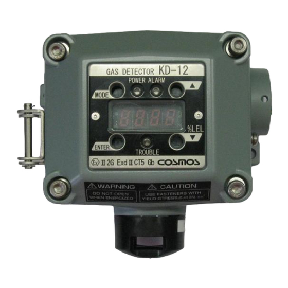
New Cosmos Electric KD-12 Instruction Manual
Diffusion type
Hide thumbs
Also See for KD-12:
- Instruction manual (40 pages) ,
- Instruction manual (40 pages) ,
- Instruction manual (46 pages)
Table of Contents
Advertisement
Quick Links
Diffusion type Gas Detector
Keep this instruction manual where it is readily accessible.
Thoroughly read this instruction manual before using the equipment so it can be used
safely and correctly.
This manual provides information concerning standard specifications. If the specifications
of your model are nonstandard, refer to the delivery specifications.
New Cosmos Electric Co., Ltd.
Model KD-12
Instruction Manual
Instruction Manual No.
GAE-056-00
July 2014
Advertisement
Table of Contents

Related Manuals for New Cosmos Electric KD-12


Summary of Contents for New Cosmos Electric KD-12
- Page 1 Thoroughly read this instruction manual before using the equipment so it can be used safely and correctly. This manual provides information concerning standard specifications. If the specifications of your model are nonstandard, refer to the delivery specifications. New Cosmos Electric Co., Ltd. Instruction Manual No. GAE-056-00 July 2014...
- Page 2 Nomenclature Replacement of Sensor Unit See pages 5 to 7. See pages 22 and 23. Wiring and Connecting Display and Operation in Methods Each Mode See pages 13 to 16. See page 19. 24 V power supply Indicator E.g., External...
-
Page 3: Table Of Contents
Table of Contents Introduction ........................ 1 Precautions ........................ 2 Contents of Package ....................4 External Dimensions and Nomenclature ..............5 4-1. Main Unit ........................ 5 4-2. Display and Control Blocks ..................6 4-3. Terminal Block ......................7 Installation ........................8 5-1. -
Page 4: Introduction
1. Introduction Thank you for purchasing the KD-12 Diffusion type Gas Detector. In order to ensure the correct and safe operation of this product, be sure to read this manual before use. This product detects oxygen leaks and oxygen deficiency in working environments of semiconductor manufacturing plants. -
Page 5: Precautions
2. Precautions Read this manual completely and be sure you understand the information provided herein before attempting to use the product. Abide by all applicable laws and regulations when using this product. WARNING Be sure to ground the product to prevent electric shocks. ... - Page 6 Depth of engagement …………………..…..10.86mm Threads engagement ……………………….6 The dimensions of flameproof joint between casing and casing cover of KD-12 flameproof housing are exceeding the minimum requirements stated EN/IEC60079-1. Please contact the manufacturer for inspection, repair and/or adjustments of this...
-
Page 7: Contents Of Package
Note: 1. A hexagon wrench, Instruction Manual, and MJ-1 Magnetic Stick are provided for each order. 2. The optional items are for use only with KD-12. WARNING Do not use the magnetic stick for any purposes other than the operation of this product. -
Page 8: External Dimensions And Nomenclature
4. External Dimensions and Nomenclature 4-1. Main Unit Number Name Description Casing cover Casing Sensor unit Incorporates a gas sensor. Ground terminal Used when grounding the frame. State display Indicates the power supply state (green), alarm state (red), and indicator trouble state (yellow). -
Page 9: Display And Control Blocks
4-2. Display and Control Blocks Magnetic switches (Insert the magnetic stick to operate the magnetic switches.) Number Name Description Makes adjustments and settings or cancels the operation of MODE switch the product. ENTER switch Enters settings or completes the control of the product. Makes adjustments and settings or increases set values and ▲switch other values. -
Page 10: Terminal Block
4-3. Terminal Block 24V(+) POWER - 4~20mA Signal + Ground Clamp terminal Lever Sensor connector O-ring Number Name Description 24 V (+) Power supply voltage (positive) Power supply voltage (-) and analog signal (negative) common Signal 4- to 20-mA (+) analog signal External contact Ground terminal Used to ground the frame. -
Page 11: Installation
Unused apertures shall be closed with suitable ATEX certified blanking elements. Fastener type M5 x 16 shall have a yield stress factor of min. 450 N/mm2. The dimensions of flameproof joint between casing and casing cover of KD-12 flameproof... - Page 12 CAUTION Be careful not to damage the gas detector when installing it. Otherwise, the explosion-proof performance of the gas detector will be lost. Do not install the product in the following places. - Places where the ambient temperature exceeds the operating temperature range (10C to 40C).
- Page 13 Mount the main unit to the wall with the M5 screws that are provided with the product. Be sure to install the protective cover (optional) when mounting the main unit outdoors. Mount the main unit with a 2B pole mounting bracket (optional) when mounting the main unit to a 2B pole.
-
Page 14: Examples Of Installation Positions
5-2. Examples of Installation Positions Install the product in places where gas easily accumulates. Places where gas easily accumulates. Gas detector Roof fan Entrances and windows (Exhaust port) (Suction and exhaust ports) Entrance Gas detector (Suction port) mounting position Plan view Side view Example of Installation Position... -
Page 15: Mounting Of Optional Items
5-3. Mounting of Optional items Protective Cover Horizontal Type (KW-41) Vertical Type (KW-42) CAUTION Secure the casing cover with M3 screws if strong winds are expected. 2B Pole Mounting Bracket... -
Page 16: Wiring Method
6. Wiring Method 6-1. Wiring Work Be sure to provide explosion-proof wiring if the product is to be used in a hazardous area. WARNING The cable entry device and blanking elements shall be of ATEX certified in type of explosion protection flameproof enclosure ‘’d’’, suitable for the condition of use and correctly installed. -
Page 17: Wiring And Connection
6-2. Wiring and Connection WARNING Before opening the casing cover of the gas detector, be sure to turn off the product and all devices (e.g., indicator unit and signal converter) connected to the product. If the power is turned ON, the power supply may become a source of ignition. ... - Page 18 Not grounded terminals Grounded System Configuration Example Single detector connected Multiple detectors monitored to indicator unit together Detector Detector Indicator unit KD-12 Security management system KD-12 KD-12 VISION S-500 KD-12 Comprehensive gas detection/alarm system KD-12 For details, refer to the Instruction Manual of each device.
- Page 19 6-2. Wiring and Connection (Continued) Typical Connection Procedure Prepare a power supply that can provide 24 V. (Do not turn on the power supply before wiring the main unit.) Loosen the hexagon socket bolts on the four corners of the main unit using the provided hexagon wrench with a nominal diameter of 4 mm, and open the casing cover of the main unit.
-
Page 20: Precautions Before Use
7. Precautions before Use CAUTION Before turning ON any of the devices (e.g., indicator unit, signal converter) connected to the product, recheck that all of the connections are correct. Make sure that the gas detector and indicator unit or signal converter, in particular, are connected properly. In Case of Oxygen Deficiency ... -
Page 21: Display At Start-Up (Initial Delay)
8. Display at Start-up (Initial Delay) CAUTION If the sensor output is not stable, the external contact point may operate after the initial delay. Release the interlock of the external equipment if necessary. During the initial delay, there is a fixed output of the analog signal corresponding to the standard oxygen concentration 21.0 vol%. -
Page 22: Display And Operation In Each Mode
9. Display and Operation in Each Mode In excess of alarm set value Maintenance mode At start-up Gas monitor Test mode Gas monitor (Initial delay) mode Test mode mode Green lamp Red lamp Red lamp lamp Green flashes flashes flashes Green flashes lamp is... -
Page 23: Trouble Alarm
10. Trouble Alarm The product has a self-inspection function, and the trouble alarm will operate if a problem occurs. The product will inform the user of the problem details with the display shown in the following table when the trouble alarm operates. ... -
Page 24: Maintenance Check And Operation Method
11. Maintenance Check and Operation Method 11-1. Daily Inspection and Periodical Inspection Daily inspections are conducted by the user, while periodical inspections are conducted by your local representative. Frequency Checking item Contents of inspection ▪ The status of lamp (green POWER indicator) is lit. -
Page 25: Replacement Of Sensor Unit
If the sensor and the detector are incorrectly connected, the detector cannot detect gas. The dimensions of flameproof joint between casing and casing cover of KD-12 flameproof housing are exceeding the minimum requirements stated EN/IEC60079-1. Please contact the manufacturer for inspection, repair and/or adjustments of this flameproof. - Page 26 11-2. Replacement of Sensor Unit (Continued) Turn OFF the power supply to the Detector. Remove the sensor casing cover by rotating it in the direction of the arrow. (See the photograph below on the left.) Pull down the sensor to remove it. (See the photograph below on the right.) Connect the sensor.
-
Page 27: Calibration Method
11-3. Calibration Method Maintenance Mode CAUTION While in maintenance mode, the external contact does not operate when the concentration of gas reaches or exceeds the alarm set value. The product in maintenance mode maintains the current status while the display shows [ This mode is canceled by repeating the same operation(1 to 4), turning the product OFF, or waiting 8 hours. -
Page 28: Span Rough Adjustment
Span Rough Adjustment This adjustment mode is used after replacing the sensor or when adjustment cannot be performed with the 21.0 vol% adjustment. CAUTION The external contact may operate during span rough adjustment. Before performing span rough adjustment, set the product to maintenance mode or release the interlocks of the external devices if needed. -
Page 29: Vol% Adjustment
21.0 vol% Adjustment ・This span adjustment mode is used in atmospheric air during periodic inspection. WARNING ▪ Always perform the 21.0 vol% adjustment in clean air. If you perform the 21.0 vol% adjustment in a gas atmosphere, the value of oxygen concentration output will be displayed incorrectly. -
Page 30: Full-Scale And Alarm Set Value Display
Full-scale and Alarm Set Value Display The full-scale and alarm set values are only displayed. They cannot be changed. While in gas monitor mode, press the MODE switch of the main unit first. Then press the UP switch with the magnetic stick within approximately 2 seconds. The main unit displays first, and displays (The product is ready to work but nothing has been operated.) -
Page 31: Test Mode
Test Mode ・Test values are adjusted and used for tests in this mode. CAUTION The external contacts may operate while the Detector is in test mode. Before changing the Detector to test mode, set the Detector to maintenance mode as required. -
Page 32: Troubleshooting
12. Troubleshooting Before requesting repairs, refer to the following table. Consult your New Cosmos representative if the product does not return to normal after taking the corresponding remedies shown below or if the defective condition is not found in the table. ... -
Page 33: Specifications
II 2 G Ex d IIC T5 Gb) EMC : EN61000-6-4:2001, EN50270:2006 - Type 2 Performance testing : The measuring function of the KD-12 gas detector for explosion protection, according to Annex II clause 1.5.5, 1.5.6 and 1.5.7 of the Directive 94/9/EC, is not covered in this certificate. -
Page 34: Markings Of Explosion-Proof
Power supply 24VDC (18 to 30 VDC) Power consumption 3W max. Size 158 (W) x 120 (H) x 68 (D) mm (excluding protruding parts) Weight Approx. 1.3kg Mounting method Wall mounting The above specifications are subject to change without notice. If your specifications are nonstandard, refer to the delivery specifications. -
Page 35: Warranty
15. Warranty New Cosmos Electric Company Limited (hereafter referred to as “New Cosmos”) offers the following as the sole and exclusive limited warranty available to the Customer. This warranty is in lieu of, and the Customer waives, all other warranties of any kind or nature, expressed or implied, including without limitation any warranty for merchantability or fitness for a particular purpose. -
Page 36: Glossary
16. Glossary Detector: A unit that detects gas concentration and converts it to electric signals. Diffusion type: A method to detect gas by utilizing convection and diffusion of gas. Explosion proof construction: A totally enclosed structure. When an explosive gas explodes in a container, the container can resist the pressure and prevent the ignition of explosive gases outside of it. - Page 38 Revision GAE-056-00 July 2014 Additional copies of this Instruction Manual are available. Contact the following address for ordering information. Distributor: Manufacturer: New Cosmos Electric Co., Ltd. 2-5-4 Mitsuya-naka Yodogawa-ku Osaka 532-0036, Japan Phone 81-6-6309-1505 Fax 81-6-6308-0371 Email e-info@new-cosmos.co.jp http://www.new-cosmos.co.jp New Cosmos Electric Co., Ltd.
Need help?
Do you have a question about the KD-12 and is the answer not in the manual?
Questions and answers