Table of Contents
Advertisement
Quick Links
SUCTION TYPE GAS DETECTOR
Instruction Manual
Keep this manual for easy reference.
Carefully read this manual prior to use.
This manual describes the standard model. If your unit has end-user-specific
options, this manual will be superseded by your delivery specifications.
PE-2CC
PE-2DC
Instruction Manual No.
GAE-122-01
March 2023
Advertisement
Table of Contents

Subscribe to Our Youtube Channel
Related Manuals for New Cosmos Electric PE-2CC


Summary of Contents for New Cosmos Electric PE-2CC
- Page 1 SUCTION TYPE GAS DETECTOR PE-2CC PE-2DC Instruction Manual Keep this manual for easy reference. Carefully read this manual prior to use. This manual describes the standard model. If your unit has end-user-specific options, this manual will be superseded by your delivery specifications.
-
Page 2: Table Of Contents
Table of Contents Introduction ..........................1 General Precautions ........................ 2 Package Contents ........................3 Unit Dimensions and Components ..................4 Installation ..........................5 Wiring ............................ 8 6-1. Wiring Connection ......................8 6-2. Wiring and Connection ....................11 Before Use ..........................13 7-1. -
Page 3: Introduction
To ensure reliable operation, please read this instruction manual prior to use. The difference between PE-2CC and PE-2DC is the power source for the pump. The PE-2CC requires 100 VAC, while the PE-2DC requires 24 VDC for the pump’s power source. -
Page 4: General Precautions
2. General Precautions Carefully read this manual prior to use. Follow the precautions below to ensure safe operation. Only wire/install/use this product in accordance with applicable laws and regulations. Only a qualified electrician with knowledge of wiring and installation procedures should perform wiring and installation. -
Page 5: Package Contents
This product is packed and shipped with the utmost care. If any items are missing or damaged, please contact New Cosmos or its distributor for replacement. Item Qty. Gas detector (PE-2CC or PE-2DC) Per your order Instruction manual (this document) 1 per order... -
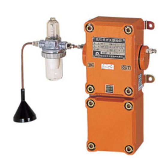
Page 6: Unit Dimensions And Components
4. Unit Dimensions and Components ④ Ground terminal Ground terminal Figure 1. Outer Appearance Item Component Qty. Description Case Terminal case Manifold plate PT1/8(Rc1/8) ⌀6 Half joint Mounting bracket Gas sensor Suction pump Terminal block Hex screw (M10) Name plate... -
Page 7: Installation
5. Installation CAUTION Joint surfaces are important members for ensuring the explosion-proof performance of the product. Do not damage or strike joint surfaces during installation. Keep joint surfaces clean and free from any damage. Contaminates such as scratches, fingerprints, dirt and oil may adversely affect the explosion-proof characteristics of the product. - Page 8 Installation Height Gas type Installing height Remarks Gas heavier than air Maximum of 10cm above Determine the height by (e.g., LPG) the floor considering easy maintenance and inspection. Gas near the specific 75 to 150 cm above Determine the height by gravity as air the floor considering the specific...
- Page 9 Figure 3. In Piping Pit Figure 4. At Elevated Location CAUTION Install the collecting cone above any water so that it will not be drawn in. Protective Cover and Auto Drain Installation Figure 5. Protective Cover Figure 6. Auto Drain CAUTION Secure the protective cover in the event of forecasted high winds, storm, or a typhoon.
-
Page 10: Wiring
6. Wiring Please refer to the indicator unit’s instruction manual along with this manual. 6-1. Wiring Connection Perform explosion-proof enclosure wiring when installing the gas detector in a hazardous area. (1) Wiring up to this product (here explained in case of using rigid steel conduits method) CAUTION ... - Page 11 Use parallel pipe threads (JIS B 0202) for connections between conduits, fittings, and joint boxes. This gas detector comes with PF3/4 female threads (G3/4). Engage at least five threads per connection, and then firmly tighten with a lock nut. Figure 7. Typical Layout (2) Wiring connection to this product There are two wiring connection methods, rigid steel conduit method and pressure-resistant gasket type cable gland method.
- Page 12 Use cable whose outer diameter matches the inner diameter of the gasket by referring to the table below. Fully tighten the cable gland, to prevent the formation of a flame path for explosive gas or fire. Cable outer dia. Gasket inner dia.
-
Page 13: Wiring And Connection
Connect so that the PA and PB terminals should be respectively positive and negative. The required power supply for the pump is different between PE-2CC and PE-2DC. 100VAC is required by PE-2CC and 24VDC by PE-2DC. Wire the correct source. - Page 14 Indicator Unit Terminal Block Gas Detector Terminal Block Pump Power Supply AC100V Gas Detector Figure 9. PE-2CC Wiring Diagram Indicator Unit Terminal Block Gas Detector Terminal Block PA (+) Pump Power Supply 24VDC PB (-) Gas Detector Figure 10. PE-2DC Wiring Diagram...
-
Page 15: Before Use
7. Before Use CAUTION Before turning on the unit, check that all the components are connected correctly. The markings on the indicator unit and gas detector must match. 7-1. Precautions during Use DANGER Do not place your face closer to the exhaust port of the gas detector. Deoxygenated air or gas harmful to humans may be inhaled. -
Page 16: Maintenance
8. Maintenance Routine checks are carried out by the user, while annual inspections are performed by New Cosmos or its authorized representative. 8-1. Routine Check (1) Visual check (min. one per month) Check the gas detector for corrosion. Check the mounting brackets, screws, fittings, piping, etc. for corrosion. Visually check and replace any worn or damaged parts. -
Page 17: Annual Inspection
8-2. Annual Inspection (min. one per year) Important Notice for Annual Inspection In order to ensure the reliability of the gas detection and alarm system, it is vital to perform periodic maintenance and inspections. Further, it is necessary to perform inspections and calibrations by using actual gas (combustible or poisonous gas). - Page 18 (B) When a commercially prepared gas cylinder is not available, Use a gas calibration kit (not included) and a pure gas cylinder (isobutane at 99vol% or more). Dilute pure isobutane with air to produce 0.9vol% (50%LEL) calibration gas. DANGER Ensure that there is no open flame or source of ignition when handling a flammable gas with the concentration exceeding the LEL.
-
Page 19: Gas Sensor Replacement
Color combination defers depending on the sensor type. Tighten the terminal screws (M3x8) to secure the lead wires. (7) Install the top cover in the electronics case and tighten the four hex screws (M10). Return used gas sensors to New Cosmos Electric. - Page 20 Catalytic combustion sensor Lead wire from sensor Terminal Lead wire from terminal case Pink Black Black White White Green Hot wire semiconductor sensor Lead wire from sensor Terminal Lead wire from terminal case Orange Black Black White White Green Thermal Conductivity sensor Lead wire from sensor Terminal Lead wire from terminal case...
-
Page 21: Filter Replacement
8-5. Filter Replacement If the disposable filter inside the filter unit (FC-32) is dirty, replace it with a new one. A dirty filter will result in a decreased flow rate. (1) Loosen the clamp ring to remove the cup and ring gasket. (2) Pull and twist the filter to take it off. - Page 22 (1) Remove the two hex screws (M5x15 and M6x15) with spring washers from the unit with the hex wrenches (M5 and M6). (2) Slowly remove the manifold plate. Remove the three ring gaskets (P5, P6 and TPG-6). (3) Clean the manifold plate and gas detector’s surface with a soft cloth to remove dust and dirt.
-
Page 23: Specifications
9. Specifications Model PE-2CC PE-2DC Pump power 100 VAC 24 VDC Sampling method Suction type Detection principle Catalytic combustion sensor, Hot wire semiconductor sensor, or Thermal conductivity sensor Target gas and indication range As per delivery specification. Number of cores... -
Page 24: Detection Principles
(2) Failures and damages caused by disaster, earthquake, storm and flood, lightning, extreme climate, abnormal power supply voltage, excessive electromagnetic interferences, or other acts of God. (3) Failures and damages resulting from repair and/or modification by non-New Cosmos certified technicians. (4) Consumables and failures and damages resulting from improper consumable replacement. -
Page 25: Thermal Conductivity Sensor
Sensor element Figure 18. Hot Wire Semiconductor Sensor 11-3. Thermal Conductivity Sensor A thermal conductivity sensor is based on the principle that some gases have a different thermal conductivity from air. When a gas comes in contact with a heated platinum coil coated with an inert substance (sensor element), the gas will conduct the heat from the coil more or less efficiently than air. -
Page 26: Glossary
12. Glossary Term Definition Flow meter Equipment for measuring the flow rate in the piping. Collecting cone Use for increased gas collection efficiency, and as a water deflection at the sampling port. Connected to the end of the sampling pipe/tube. Dust and water proof. Flameproof enclosure Enclosure in which the parts which can ignite an explosive (explosion-proof enclosure) - Page 27 This page intentionally left blank...
- Page 28 March 2018 Original issue GAE-122-01 March 2023 Additional copies of this instruction manual may be purchased. Contact New Cosmos or its authorized representative for ordering. Authorized representative: Manufacturer: NEW COSMOS ELECTRIC CO., LTD. 2-5-4 Mitsuya-naka, Yodogawa-ku, Osaka 532-0036, Japan www.newcosmos-global.com...
Need help?
Do you have a question about the PE-2CC and is the answer not in the manual?
Questions and answers