Table of Contents
Advertisement
Quick Links
Diffusion Type Gas Detector
KD-12HT series
Instruction Manual
Keep this manual for easy reference.
Carefully read this manual prior to use.
This manual describes the standard model. If your unit contains customer-specific
options, the delivery specifications will supersede this manual.
Instruction Manual No.
GAE-162-02
September 2022
Advertisement
Table of Contents

Related Manuals for New Cosmos Electric KD-12HT Series


Summary of Contents for New Cosmos Electric KD-12HT Series
- Page 1 Diffusion Type Gas Detector KD-12HT series Instruction Manual Keep this manual for easy reference. Carefully read this manual prior to use. This manual describes the standard model. If your unit contains customer-specific options, the delivery specifications will supersede this manual.
- Page 2 Unit Dimensions and Sensor Unit Replacement Components Pages 30 and 31 Pages 5 to 9 Wiring Display and Operation Modes Pages 13 to 17 Page 19 24 V power supply Indicator E.g., External Shield alarm Earth terminals ...
-
Page 3: Table Of Contents
Table of Contents Introduction ........................1 General Precautions ...................... 2 Package Contents ......................4 Unit Dimensions and Components ................5 4.1. Exterior Appearance (KD-12HT-T) ................. 5 4.2. Exterior Appearance (KD-12HT-L) ................. 6 4.3. Exterior Appearance (Main Body) ................7 4.4. Display and Controls ....................8 4.5. -
Page 4: Introduction
Introduction Thank you for purchasing the New Cosmos KD-12HT series diffusion type gas detector. Before use, please read this instruction manual carefully to ensure safe and reliable operation. There are two models depending on the probe shape (straight and L-shaped), KD-12HT-T and KD-12HT-L. -
Page 5: General Precautions
General Precautions Carefully read this manual prior to use. To ensure safe operation, follow the precautions below. Only use this product in accordance with the applicable laws and regulations. WARNING Ground the detector to prevent electric shocks. ... - Page 6 CAUTION Wiring and installation should only be performed by a qualified electrician with knowledge of wiring/installation procedures. Explosion-proof wiring and installation should only be performed by a qualified electrician with knowledge of explosion-proof components/installation procedures. Do not disassemble, modify, or alter the structure of this unit or its electrical circuits. ...
-
Page 7: Package Contents
Package Contents A standard package consists of the following items. If any items are missing or damaged, please contact New Cosmos or its authorized representative for replacement. Standard package Optional Items Gas detector Calibration cap (GCP-09) Gas calibration kit (Z-001K) Accessory kit 2-bulb hand pump Gasket (dia. -
Page 8: Unit Dimensions And Components
Unit Dimensions and Components 4.1. Exterior Appearance (KD-12HT-T) ③ Main body Probe (Dimensions are in mm) Item Component Description/Function Main body Used for grounding the frame Earth terminal (external) Thread size: G3/4 or PF3/4 Pitch: 1.81 mm Min. depth of engagement: 10.86 mm Cable entry Min. -
Page 9: Exterior Appearance (Kd-12Ht-L)
4.2. Exterior Appearance (KD-12HT-L) ③ Main body Probe (Dimensions are in mm) Item Component Description/Function Main body Used for grounding the frame Earth terminal (external) Thread size: G3/4 or PF3/4 Pitch: 1.81 mm Min. depth of engagement: 10.86 mm Cable entry Min. -
Page 10: Exterior Appearance (Main Body)
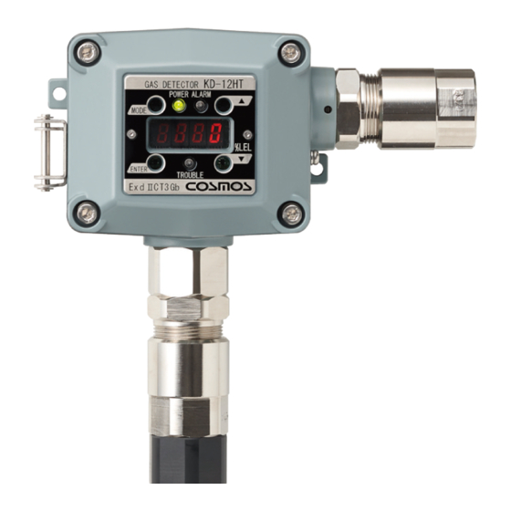
4.3. Exterior Appearance (Main Body) ④ (Dimensions are in mm) Item Component Description/Function Indicate the status of the unit: Status LED (3 places) power (green), alarm (red), and fault (amber) Insert the magnetic stick into each magnetic switch Magnetic switch (4 places) opening to operate Displays the gas concentration, parameter value and Display... -
Page 11: Display And Controls
4.4. Display and Controls ⑥ ⑦ KD-12 KD-12HT ③ GAS DETECTOR ① POWER ALARM MODE ⑤ ④ ② ENTER TROUBLE ExdⅡCT5 ⑧ Magnetic Switches Use the magnetic stick (MJ-1) to operate the magnetic switches. Item Component Description/Function Changes the operation mode or cancels the current MODE switch operation ENTER switch... -
Page 12: Terminal Block
4.5. Terminal Block Terminal block 24V(+) POWER - 4~20mA Signal + Earth terminal Slot Lever (internal) レバー クランプ (5 places) (5 places) Gasket Sensor connector Item Name Description/Function 24 V (+) Power supply voltage (+) Power supply voltage (-) and analog signal (-) common Signal 4-20mA analog signal (+) External relay contact... -
Page 13: Installation
Installation 5.1. Guideline WARNING Before opening any part of the gas detector, ensure no explosive atmosphere is present. The cable gland (not included) shall be ATEX/UKEx/IECEx-certified as “Flameproof Enclosure ‘db’”, and shall meet the special conditions of use on page 2. ... - Page 14 Secure the gas detector to the mounting location (e.g., furnace’s wall) by using the flange. The flange specifications are given below. The sensor unit’s outside diameter is HEX32. The mounting hole which the sensor unit and probe fit through should be 36 mm in dia. or more. For fine adjustment of the direction of the detector face, untighten the two hexagonal screws to adjust the face to the right position, and then retighten the screws to firmly secure the detector.
- Page 15 The case cover of the detector needs be able to open during installation, wiring, or sensor replacement. Make sure to keep sufficient space so that the cover can be opened to 90° or more. (Dimensions are in mm)
-
Page 16: Wiring
Wiring 6.1. Guideline Use explosion-proof wiring when installing the detector in a hazardous area. WARNING Before opening any part of the gas detector, ensure no explosive atmosphere is present. The cable gland (not included) shall be ATEX/UKEx/IECEx-certified as “Flameproof Enclosure ‘db’”, and shall meet the special conditions of use on page 2. -
Page 17: Wiring/Connection
6.2. Wiring/Connection WARNING Before opening the case cover of the gas detector, be sure to eliminate possible source of ignition. Disconnect the power supply to the detector and all devices connected to it (e.g., indicator unit and signal converter). ... - Page 18 Typical System Configuration Gas detectors KD-12 Security control Gas detection system system Gas detector Indicator unit KD-12 KD-12 vision S-500 KD-12 KD-12 One to one configuration Monitoring multiple detectors Figure 6-2. Typical System Configuration Refer to the instruction manual of each device for full information. External Earth Terminal Connection WARNING ...
- Page 19 Terminal Block Wiring Procedure CAUTION Do not touch or let any tool (e.g., flat-head screwdriver, wrench) touch the inside surface of the case or case cover. Keep joint surfaces clean and free from any damage. Contaminates such as scratches, fingerprints, dirt and oil may adversely affect the explosion-proof characteristics of the device.
-
Page 20: Precautions Before Use
(5) Insert the tip of each wire into the slot. Connect the (PWR+) wire to the slot marked “ 24V(+)” . Connect the (PWR-) wire to the slot marked “GND ” . Connect the (Analog 4-20mA) wire to the slot marked “Signal ” . As needed, connect the external relay contact wires to the slots marked “ZA ”... -
Page 21: Display At Power-Up (Warm-Up)
Display at Power-up (Warm-up) CAUTION Check that there is no gas present before powering on the gas detector. When the sensor output is not stable, the external relay contact may possibly activate. To prevent possible activation of the external relay contact after the warm-up is complete, release the interlocks of the external devices, if needed. -
Page 22: Display And Operation Modes
Display and Operation Modes When the alarm set value is exceeded Maintenance mode Power-up Gas monitoring Test mode (Warm-up) mode monitoring Test mode mode Red LED Red LED Green LED blinks Green blinks Red LED blinks blinks Green LED is lit LED is lit Green LED is lit Display... -
Page 23: Trouble Alarms
Trouble Alarms This product has a self-diagnosis function, and a trouble (fault) alarm will activate if a problem is found. This product alerts the user of a problem by showing the corresponding error code on the display when a trouble alarm activates. The error codes are listed in the table below. ... -
Page 24: Maintenance, And Operational Checks/Procedures
Maintenance, and Operational Checks/Procedures 11.1. Routine Check and Annual Inspection Routine checks are carried out by the user, while annual inspections are performed by New Cosmos or its authorized representative. Frequency Item Procedure Check that POWER LED (green) is lit. ... -
Page 25: Calibration Gas Preparation
11.2. Calibration Gas Preparation Prepare calibration gas (actual gas) for inspection or maintenance use. Typical method to prepare calibration gas, toluene, is given below as an example. (1) Required tools and items Toluene reagent Gasbag with two openings Gas sampling bag Syringe Measuring pump... - Page 26 DANGER Ensure that there is no open flame or source of ignition when handling a flammable gas. (4) Check the gas concentration value of he prepared gas. a. Check that the reagent inside the gasbag completely evaporates. b. Use a portable gas detector to measure the concentration value from the outlet of the gasbag.
-
Page 27: Calibration
11.3. Calibration CAUTION For calibration with actual gas, the detector needs to be removed from the external equipment (e.g., drying furnace). For calibration, use the dedicated calibration cap (sold separately). After use in connection with a high-temperature furnace, the probe and its surrounding area become very hot. -
Page 28: Zero Adjustment
Zero Adjustment CAUTION To prevent possible activation of the external relay contact during the zero adjustment, set the detector to maintenance mode or release the interlocks of the external devices, if needed. Perform a zero adjustment in a place where there is no target or interfering gas in the ambient atmosphere. -
Page 29: Fine Span Adjustment
Fine Span Adjustment CAUTION To prevent possible activation of the external relay contact during the fine span adjustment, set the detector to maintenance mode or release the interlocks of the external devices, if needed. Only New Cosmos technician or personnel who have completed a maintenance seminar can perform a span adjustment. -
Page 30: Coarse Span Adjustment
Coarse Span Adjustment Perform coarse span adjustment, if is displayed. CAUTION To prevent possible activation of the external relay contact during the coarse span adjustment, set the detector to maintenance mode or release the interlocks of the external devices, if needed. ... -
Page 31: Full-Scale And Alarm Set Values Display
Full-scale and Alarm Set Values Display NOTE Use the magnetic stick for the switch operation. Carefully handle the magnetic stick during operation or setting, because it has a strong attractive force. Refer to 3 “Package Contents” for full information. ... -
Page 32: Test Mode
Test Mode Test mode is used to set the test value. CAUTION To prevent possible activation of the external relay contact during the test mode, set the detector to maintenance mode or release the interlocks of the external devices, if needed. -
Page 33: Sensor Unit Replacement
11.4. Sensor Unit Replacement WARNING Disconnect the power supply to the gas detector before replacing the sensor unit. Failure to do so may cause a source of ignition. CAUTION Only New Cosmos technician or personnel who have completed a maintenance seminar can replace the sensor unit. - Page 34 The sensor unit is different depending on the detector model. Use an appropriate sensor unit. Detector model Sensor unit type KD-12HT-T EK-12HT-T KD-12HT-L EK-12HT-L 4mm hexagonal head Sensor unit screw (4 places) Flange Flange Sensor unit KD-12HT-T KD-12HT-L...
-
Page 35: Troubleshooting
Troubleshooting Before requesting repair, please refer to the table below. If the detector does not return to normal after performing the corresponding steps in the table, or if your issue is not found in the table, consult New Cosmos or its authorized representative. ... -
Page 36: Specifications
Specifications Model KD-12HT-T KD-12HT-L Detection principle Catalytic sensor Diffusion type Sampling method Target gas N-Methyl-2-Pyrrolidone (NMP) 0-100%LEL Detection range Four-digit seven-segment LED display Gas concentration display As per delivery specifications Alarm set value 25% of alarm set value under identical conditions Alarm accuracy Alarm delay Less than 30 seconds with a gas concentration that is 1.6 times higher... - Page 37 Operating temperature and Main body: -10C to 50C humidity Probe: 0C to 160C 10% to 90%RH at 0C to 50C No sudden temperature or humidity changes. No condensation Power supply 24 VDC (18 to 30 VDC) 1.5 W during normal operation (Max. 3 W) Power consumption Dimensions 127 (W) x 530 (H) x 68 (D) mm...
- Page 38 External markings for explosion-proof Nameplate detail Serial number label detail Rating label detail Certificate label detail Warning label detail Harmonised/Designated standards EN IEC 60079-0:2018 EN 60079-1:2014 IEC 60079-0:2017 Edition 7.0 IEC 60079-1:2014 Edition 7.0...
-
Page 39: Warranty
Warranty The warranty period is one (1) year from the date of purchase. You are entitled to the limited warranty, if the product malfunctions due to a manufacturing defect during normal use in accordance with the instruction manual, specifications and labels. 1. -
Page 40: Detection Principles
Detection Principles Catalytic Sensor Catalytic combustion occurs on the catalytic layer applied on a platinum coil even if the gas concentration is well below the lower combustion limit. This causes a rise in temperature of the platinum coil and increases its electrical resistance. This change is read as a differential voltage using a bridge circuit. - Page 41 This page intentionally left blank...
- Page 42 Initial issue GAE-162-01 September 2021 GAE-162-02 September 2022 Additional copies of this instruction manual may be purchased. Contact New Cosmos or its authorized representative for ordering. Authorized representative: Manufacturer: NEW COSMOS ELECTRIC CO., LTD. 2-5-4 Mitsuya-naka, Yodogawa-ku, Osaka 532-0036, Japan www.newcosmos-global.com...
Need help?
Do you have a question about the KD-12HT Series and is the answer not in the manual?
Questions and answers