Table of Contents
Advertisement
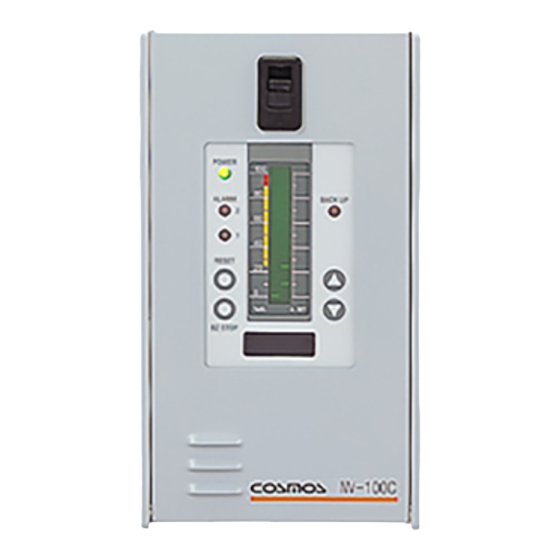
1 Point type Combustible Gas Detection /
Alarm System
Model NV-100C
Instruction Manual
● Keep this instruction manual where it is readily accessible.
● Thoroughly read this instruction manual before using the equipment so it can be used safely and correctly.
New-Cosmos Electric Co., Ltd.
Instruction manual No.
GAE-009-01
December 2004
Advertisement
Table of Contents

Related Manuals for New Cosmos Electric NV-100C


Summary of Contents for New Cosmos Electric NV-100C
- Page 1 1 Point type Combustible Gas Detection / Alarm System Model NV-100C Instruction Manual ● Keep this instruction manual where it is readily accessible. ● Thoroughly read this instruction manual before using the equipment so it can be used safely and correctly.
-
Page 2: Table Of Contents
Table of Contents 1. Introduction......................................1 2. Safe Operation....................................1 3. Unpacking......................................2 4. System Structure....................................3 5. Dimensions and Part Names ................................4 5-1 Indicator and Alarm Unit ................................4 5-2 Gas Detector .....................................6 6. Installation and Wiring ..................................8 6-1 How to Install the Indicator and Alarm Unit..........................8 6-2 How to Install the Gas Detector ............................10... -
Page 3: Introduction
1. Introduction Thank you for purchasing a NV-100C single-point combustible gas detection /alarm system. This system is used to prevent leakage of combustible gas. This equipment continuously monitors for leakage of combustible gas, and indicates when a preset level has been exceeded by a lamp and sound. -
Page 4: Unpacking
Parts to embed the panel (embedded panel only) Air filter FC-32 with flow checker (for Suction type gas detector head only) Sample gas collector PE-N3(for Suction type gas detector head only) NV-100C instruction manual (this book) Test results of the equipment Options (separately sold) Rainproof KW-15 for Diffusion type gas detector head KD-5□-N... -
Page 5: System Structure
4. System Structure This equipment consists of a part that detects gas (gas detector head) and a part that indicates gas concentration and sets off an alarm (indicator and alarm unit). The parts are connected by cables. Indicator and alarm unit NV- 100C Power source... -
Page 6: Dimensions And Part Names
5. Dimensions and Part Names 5-1 Indicator and Alarm Unit 71.5 18 19 20 21 23 24 25 POWER ALARM BACKUP RESET A.SET BZ STOP TB BZ PA PB 2‑φ6 Fig. 2 Dimensions of the Indicator and Alarm Unit (without a backup power source) FUSE... - Page 7 Name Function This LCD bar graph meter with backlight indicates gas concentration and the Gas concentration indicator preset alarm value. The peak value continues to blink even after the reading value goes down after an alarm. It is green during normal operation and orange when the sensor failure. It Power lamp (POWER) blinks green when the equipment is turned on and also after a failure has been taken care of to show that the equipment is warming up.
-
Page 8: Gas Detector
5-2 Gas Detector (1) Diffusion type gas detector head KD-5□-N 2‑9×15 oval hole Rainproof cover KW−15 Rainproof cap KW−22 Screw Ground cover Ground Pan-head screw Saddle Stand M5phexagon socket head bolt M4phexagon socket head bolt Guard mount Sensor guard Sensor unit Terminal box cover ... - Page 9 (2) Suction type gas detector head PE-2DC 4‑ 7 ① ⑦ ④ ③ ⑥ ⑤ ⑩ ② ⑧ Grounding terminal G3/4 Name plate Terminal block Suction pump Sensor element Mount Half joint Gap plate Terminal box Detector main body Descriptions Q’ty Remark Fig.5 Suction type gas detector head...
-
Page 10: Installation And Wiring
6. Installation and Wiring 6-1 How to Install the Indicator and Alarm Unit The equipment can be hang on the wall or embedded. WARNING The indicator and alarm unit is not an explosion-proof construction. Install it in a non-hazardous area. CAUTION The indicator and alarm unit must be installed in a place where someone is always present and is easy to read so that taking countermeasures and notifying others in case of an alarm is possible. - Page 11 (2) How to embed on a panel ① Cut out a rectangular opening in the panel as shown in Fig. 7. Fig. 7 Dimensions to Cut a Panel ② Insert the equipment into the opening from front. Attach the backplate on back of the equipment using the attaching screws as shown in Fig. 8. Then, fasten it to the panel with fixing screws.
-
Page 12: How To Install The Gas Detector
6-2 How to Install the Gas Detector CAUTION The gas detector must be handled with care to avoid damaging the explosion proof construction. Do not install the Gas detector in locations listed below: -Location where the ambient temperature may drop lower than –10℃ or exceed 40℃. -Location where dew condensation may occur. - Page 13 ・How to install the fixing plates Put the gas detector head between the fixing plates (Saddle and Stand) and tighten the pan-head screw to fix. Fixing plate (saddle) Pan-head screw Fix on the wall with attached the M6 hexagon bolt and the nut. Fixing plate (stand) Fig.10 How to install the fixing plate How to install the rainproof cover (optional item) and rainproof cap(optional item)
- Page 14 (2) Suction type gas detector head Suction type gas detector should be used in locations as follows. ① Inside a piping pit or location where is shut tightly. ② Furnace sampling ③ Location where the ambient temperature is high or low ④ Location where is high Use 6φ×4φ...
-
Page 15: Wiring Method
6-3 Wiring Method Refer the gas detector’s instruction manual as well. WARNING Turn OFF the indicator and alarm unit’s power before opening the cover of the gas detector. Opening the cover when the power is on may cause a fire. Ground the equipment’s main body and gas detector. - Page 16 External switch Control device 外部スイッチ 制御機器 上段端子台 空 Upper terminal block 下段端子台 R(P) S(N) Lower terminal block 3Cケーブル 3C cable 遮断器 Breaker + − アナログ出力 Analog output 拡散式ガス検知部 Diffusion type KD-5□-N 接地 Grounding 4-20mA(1-5V) 4〜20mA (+) (−) KD‑5□‑N (1〜5V) AC100/200V (DC24V) 接地...
-
Page 17: Operating Instructions
7. Operating Instructions 7-1 Notes to Users CAUTION Make sure that all parts are correctly connected before turning on the power. Check that the terminals of the gas detector and indicator and alarm unit are correctly connected. Do not connect a load to the external alarm contact that exceeds the rated capacity. 7-2 Procedures (1) Turning ON the power ① Turn ON the Power switch. - Page 18 (4) Setting alarms Alarm value is set as you specified at the time of delivery. If you want to change it, follow the procedures below. ① Confirm that it is under the normal mode (Mode Switch 0) then press the Enter key. ② Message window displays AP 1.
-
Page 19: Operation Of The Equipment
7-3 Operation of the equipment (1) When gas is detected When gas concentration around the gas detector becomes high and the reading of the gas concentration indicating bar graph exceeds the first preset alarm value, the first Alarm lamp blinks and an alarm sound (four short beeps) is heard. -
Page 20: When An Alarm Occurs
(6) Function switches CAUTION If you change setting for function switches, the equipment cannot perform as it is supposed to, for example, alarm does not go off even when there is gas leakage. Do not change setting unless you completely understand features of Function switches. -
Page 21: Maintenance Function
Use auto zero and span adjustment daily for minor zero point and sensitivity corrections, and use analog zero and span adjustment for normal corrections. NV-100C has maintenance mode function. Select a mode using the Mode switch to use each function. Functions of modes are described in the following table. - Page 22 (1) Maintenance mode 1 Auto zero and span adjustment 1) Auto zero adjustment ① Set the Mode switch at 1 to select ② Make sure that there is no gas around the gas maintenance mode 1. detector then press down the BZ STOP key until the Power lamp goes off.
- Page 23 2) Auto span adjustment ① Set the Mode switch at 1 to select ② Set the auto span preset value (any number maintenance mode 1. between 10 and 100) using the Alarm Setting keys (△▽). POWER POWER ALARM BACKUP ALARM BACKUP RESET RESET...
- Page 24 ⑦ Finally apply the calibration gas and check to see if the calibration concentration is indicated correctly POWER Check the ALARM BACK UP calibration concentration. RESET BZ STOP CAUTION Note that a gas leak alarm and external output will be generated when calibration gas is applied in normal mode.
- Page 25 ③ The Power lamp lights up again and the auto ④ Make sure that there is no gas around the zero adjustment value is reset. gas detector. Press the enter key and simultaneously turn the zero adjustment volume (ZERO) to set the indicated value on zero.
- Page 26 ③ The Power lamp lights up again and the auto ④ Set the Mode switch at 1 to select maintenance span adjustment value is reset. mode 1. POWER POWER ALARM BACKUP ALARM BACK UP RESET RESET BZ STOP BZSTOP ⑤ Confirm that the zero point is at zero and apply ⑥ Set the Mode switch at 2 to select maintenance calibration gas to the gas detector for a minute.
- Page 27 ⑨ Release the test button and check that the ⑩ Turn the test volume while pressing the test indicated value returns to zero. button to return the indicated value to the full scale. POWER POWER Return to ALARM BACKUP the full ALARM ...
-
Page 28: Maintenance And Inspections
8. Maintenance and Inspections Maintenance and inspections are very important for the equipment because the purpose of the equipment is to secure safety. Maintenance and inspections are the users’ responsibility. We can offer regular inspections if you make a maintenance contract with us. (Contact our dealer / agency for detailed information.) 8-1 Regular Inspections (Inspections that the users are responsible for) (1) Regular inspection (daily) ① ... -
Page 29: Maintenance Inspections (Contact Our Dealer / Agency For The Inspection.)
・Apply the calibration gas to the gas detector and check if an alarm goes off. ・Check that the ALARM lamp (red) on the indicator unit blinks and an alarm sound is given. (Refer to 8-3 for how to make calibration gas.) How to apply calibration gas filter with gas detector... -
Page 30: Preparation Of Calibration Gas - When Isobutene 0.72Vol%(40%Lel)
・ Cut off the power supply and check that the alarm and indicator unit normally operates for at least 30 minutes. Battery voltage indicated on the backup power source unit should be 23V or more after 30 minutes of operation. ・... - Page 31 ① Drawing raw gas Connect a gas bag to an isobutane 99vol% cylinder and draw a little more than you actually need. vinyl tube ビニールチューブ Bend back the hose and pinch with a pinch cock so the gas does not leak from the bag. ...
-
Page 32: Replacing The Gas Sensor
(3) Calibration equipment kit (optional) ● Contact our dealer / agency for a calibration equipment kit. A kit to easily make calibration gas is also available. Please contact our dealer / agency. (Equipment included in the calibration equipment kit differs according to detectors.) quantitative pump instruction manual rubber pipe pinch cock... - Page 33 (2) Replacing the sensor of the suction type gas detector PE-2DC ① Turn OFF the MODE switch 1 on the indicator unit. ② Loosen the four hexagon socket head bolts (M10×25) that fasten the electric compartment’s cover of PE-2DC with a M10 hexagon wrench and open the cover. ③ ...
-
Page 34: Replacing The Filter (Suction Type Gas Detector)
8-5 Replacing the Filter (suction type gas detector) When the filter of a flow checker which is a part of suction type gas detector becomes dirty, replace it with a new one. If you keep using a dirty filter, it may decrease flow. ① Loosen the fastening ring and detach the cup and O ring. -
Page 35: Cleaning The Gap Plate (Suction Type Gas Detector Pe-2Dc)
8-6 Cleaning the Gap Plate (suction type gas detector PE-2DC) WARNING Turn OFF the power of the main body before cleaning the gap plate in order to prevent a fire or explosion. CAUTION Be careful not to damage the joints of the gap plate or the side of the electric compartment. Damage to these parts decreases the equipment’s explosion-proof properties. -
Page 36: Troubleshooting
9. Troubleshooting Check the following before requesting repair work. Problem Cause Action Section to refer ・Wires are not correctly ・ Check and fix wiring correctly. ・Refer to 6-3. connected. ・ The Power lamp does not ・Wires are not connected light up even after the ・Retighten the terminals. -
Page 37: Specifications
10. Specifications 10-1 Indicator and Alarm Unit Model NV-100C Principle of detection Catalytic Combustion on a Platinum Filament Gases to be detected Combustible gases Indicating range 0-100%LEL Gas concentration indicator LCD bar graph meter with back light Standard preset alarm value As specified. -
Page 38: Gas Detector
No liability is accepted for the consequential damages or reinstallation labor. Defects as defined in the above shall not include decomposition by chemical reaction (including corrosion). New Cosmos Electric Company Limited, shall not assume responsibility for contingent liability arising from alleged failure of any of its products and accessories. -
Page 39: Glossary
14. Glossary Indicator / Alarm unit: A unit that receives signals from the gas detector and indicates gas concentration and alarms. Detector: A unit that detects gas concentration and converts it to electric signals. Backup power source device: A device that supplies power to the gas detector, indicator / alarm unit in order to maintain its performance during a power failure. - Page 40 July 2002 GAE-009-01 December 2004 Additional copies of this Operation Manual are available. Contact the following address for ordering information. Distributor: Manufacturer: New Cosmos Electric Co., Ltd. 2-5-4 Mitsuya-naka Yodogawa-ku Osaka 532-0036, Japan Phone 81-6-6309-1505 Fax 81-6-6308-0371 Email e-info@new-cosmos.co.jp http://www.new-cosmos.co.jp New Cosmos Electric Co., Ltd.
Need help?
Do you have a question about the NV-100C and is the answer not in the manual?
Questions and answers