Table of Contents
Advertisement
Quick Links
GETTING STARTED GUIDE
NI Digital Waveform
Generator/Analyzer
For NI PXI/PCI-655X/654X Devices
This document explains how to install, configure, test, and set up a National
Instruments digital waveform generator/analyzer. This document applies
specifically to the NI PXI/PCI-6551/6552 (NI 655X) and the
NI PXI/PCI-6541/6542 (NI 654X). For more information on the
NI 655X/654X, such as features and programming, refer to the NI Digital
Waveform Generator/Analyzer Help at Start»Programs»
National Instruments»NI-HSDIO»Documentation»NI Digital
Waveform Generator/Analyzer Help.
Refer to the specifications document that ships with your device for detailed
specifications.
For free downloads of the most current versions of product documentation
and example programs, visit
Contents
Conventions ...............................................................................................2
1. Verifying the System Components ........................................................4
Minimum System Requirements .......................................................4
Recommended System.......................................................................4
2. Unpacking ..............................................................................................5
3. Verifying the Kit Contents.....................................................................6
Documentation...................................................................................6
EMI Gasket (NI PXI-655X Only)......................................................6
4. Installing the Software ...........................................................................6
Choose and Install Your ADE ...........................................................6
Install NI-HSDIO...............................................................................7
NI Script Editor..........................................................................7
(Optional) Install the NI Digital Waveform Editor ...........................7
July 2004
373308D-01
ni.com/instruments
.
Advertisement
Table of Contents

Related Manuals for National Instruments 655 Series


Summary of Contents for National Instruments 655 Series
-
Page 1: Table Of Contents
NI PXI/PCI-6541/6542 (NI 654X). For more information on the NI 655X/654X, such as features and programming, refer to the NI Digital Waveform Generator/Analyzer Help at Start»Programs» National Instruments»NI-HSDIO»Documentation»NI Digital Waveform Generator/Analyzer Help. Refer to the specifications document that ships with your device for detailed specifications. -
Page 2: Conventions
5. Installing the Hardware................8 Installing a PXI Module..............8 Installing a PXI Module in a CompactPCI Chassis ....9 Maintaining PXI Systems ............10 Uninstalling PXI Modules ............11 Installing a PCI Device ..............11 Maintaining PCI Systems ............12 6. Configuring and Testing in MAX............12 Using the Test Panel to Generate and Acquire Data ......14 7. - Page 3 Intel to replace ISA and EISA. PCI eXtensions for Instrumentation (PXI) is a rugged, open system for modular instrumentation based on CompactPCI, with special mechanical, electrical, and software features. © National Instruments Corporation NI Digital Waveform Generator/Analyzer Guide...
-
Page 4: Verifying The System Components
1. Verifying the System Components This section specifies the minimum system requirements and recommended system for NI-HSDIO and your digital waveform generator/analyzer. Minimum System Requirements The minimum system requirements include the following components and tools: • Pentium 200 MHz or equivalent processor •... -
Page 5: Unpacking
One of the following digital waveform generator/analyzer accessories: – NI CB-2162 single-ended digital I/O accessory – NI SMB-2163 breakout box accessory • National Instruments SMB cables, available in various styles from ni.com • Windows 2000/NT 4.0 Service Pack 6a/XP •... -
Page 6: Verifying The Kit Contents
3. Verifying the Kit Contents Verify that the kit contains the following items: ❑ DVD-sized case, which contains the following items: – NI-HSDIO (High-Speed Digital I/O) instrument driver software CD, which includes the NI Digital Waveform Generator/Analyzer Help – NI Digital Waveform Generator/Analyzer Getting Started Guide ❑... -
Page 7: Install Ni-Hsdio
. The NI DWE allows you to easily import data from popular ni.com third-party EDA programs, create your own waveforms, edit these waveforms, and view acquired waveforms. If you are using the NI DWE, install it after you install NI-HSDIO. © National Instruments Corporation NI Digital Waveform Generator/Analyzer Guide... -
Page 8: Installing The Hardware
5. Installing the Hardware To install your NI digital waveform generator/analyzer, follow the instructions in the section that describes your hardware platform. When installing your hardware, follow the instructions in this section to ensure that your device can cool itself effectively. If the device temperature rises above the optimal operating temperature range, the device disables itself, and MAX or NI-HSDIO notifies you with an error message. -
Page 9: Installing A Pxi Module In A Compactpci Chassis
PCI interface on the CompactPCI bus. Compatible operation of NI PXI modules is not guaranteed between CompactPCI devices with different sub-buses nor between CompactPCI devices with sub-buses from © National Instruments Corporation NI Digital Waveform Generator/Analyzer Guide... -
Page 10: Maintaining Pxi Systems
different vendors and PXI. The standard implementation for CompactPCI does not include these sub-buses. • The module works in any standard CompactPCI chassis adhering to the PICMG CompactPCI 2.0 R2.1 document. • When you use the NI 655X/654X as a plug-in device in a standard CompactPCI chassis, you cannot access PXI-specific functions. -
Page 11: Uninstalling Pxi Modules
6. Before operating the device, install all filler panels. Missing filler panels disrupt the necessary air circulation in the PC. 7. Replace the PC cover. 8. Plug in and power on the PC. © National Instruments Corporation NI Digital Waveform Generator/Analyzer Guide... -
Page 12: Maintaining Pci Systems
1 NI PCI Device 2 PCI Slot 3 Personal Computer Figure 2. PCI Installation Maintaining PCI Systems Inspect the onboard fan on a regular basis to prevent fan and air circulation path blockage. Cleaning frequency depends on the amount of use and the operating environment. - Page 13 Reset Device from the shortcut menu shown in Figure 3. 6. Record the device name assigned to the digital device. You need this information when you program the device. © National Instruments Corporation NI Digital Waveform Generator/Analyzer Guide...
-
Page 14: Using The Test Panel To Generate And Acquire Data
Using the Test Panel to Generate and Acquire Data To verify your device configuration, use the device test panel in MAX to generate and acquire simple digital data using your device by completing the following steps: 1. Right-click the device under NI-DAQmx Devices, and select Test Panels as shown in Figure 3. -
Page 15: Connecting Signals
NI digital waveform generator/analyzers. For more information about using the NI CB-2162, refer to the NI CB-2162 User Guide. NI also offers the NI SMB-2163 breakout box for National Instruments single-ended digital waveform generator/analyzers. The NI SMB-2163 offers coaxial SMB connectors for each channel on the DDC connector, providing an easy way to connect to other devices for testing and debugging. - Page 16 NI PXI-1042 NI PXI-6551 50 MHz Digital I/O ACCESS ACTIVE PFI 0 1 PXI Chassis with NI Digital Waveform 2 SHC68-C68-D2 Cable Generator/Analyzer 3 NI CB-2162 Accessory Figure 4. Connecting the NI CB-2162 Accessory NI PXI-1042 NI PXI-6551 50 MHz Digital I/O ACCESS ACTIVE PFI 0...
-
Page 17: Wiring For Common Measurements
Refer to the NI Digital Waveform Generator/Analyzer Help for more information about signal termination. Peripheral Device Cable NI 655 X NI CB-2162 Figure 6. Dynamic Generation Functional Diagram © National Instruments Corporation NI Digital Waveform Generator/Analyzer Guide... -
Page 18: Dynamic Acquisition
Dynamic Acquisition When performing dynamic acquisition with the NI 655X/654X, the source generating the signals needs a matched source impedance as close to 50 Ω as possible to minimize signal reflections and maintain optimal signal quality. Figure 7 shows a diagram of a dynamic acquisition system using the NI 655X as an example. -
Page 19: Programming The Digital Waveform Generator/Analyzer
For the location of example programs that you can use as a basis for your first NI-HSDIO program, refer to Programming»Getting Started with NI-HSDIO in the NI Digital Waveform Generator/Analyzer Help. © National Instruments Corporation NI Digital Waveform Generator/Analyzer Guide... -
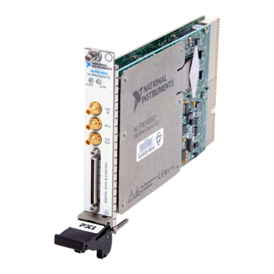
Page 20: Appendix A: Device Front Panels
Appendix A: Device Front Panels The NI 655X/654X front panels contain four connectors—three SMB jacks (CLK IN, PFI 0, and CLK OUT) and one 68-pin VHDCI connector (DIGITAL DATA & CONTROL, or DDC). Figure 8 shows the NI 6541 front panels and pinout, which are identical to those of the NI 6542. - Page 21 34, 36, 38, 40, 42, 44, 46, 48, 50, 54, 56, 58, 62, 66 8, 52, 60 RESERVED N/A These terminals are reserved for future use. Do not connect to these pins. © National Instruments Corporation NI Digital Waveform Generator/Analyzer Guide...
- Page 22 Figure 9 shows the NI 6551 front panels and pinout, which are identical to those of the NI 6552. The DDC signals are described in Table 2. The SMB connectors are described in Table 3. The LEDs are described in Tables 4 and 5.
- Page 23 62, 66 1, 3, 5, 7, 8, 9, RESERVED N/A These terminals are reserved for future 11, 35, 37, 39, use. Do not connect to these pins. 41, 43, 45, 52, © National Instruments Corporation NI Digital Waveform Generator/Analyzer Guide...
- Page 24 Table 3. NI 654X/655X SMB Connectors Signal Signal Connector Name Type Description CLK IN Reference/ Control Terminal for the external Reference Clock Input clock used for the PLL or for the external Sample clock used for pattern generation and/or acquisition. PFI 0 Programmable Control...
-
Page 25: Appendix B: Troubleshooting
3. If the device is still not listed, power down the system, ensure the device is correctly installed, and restart. 4. If the device still does not appear under NI-DAQmx Devices, contact NI support at ni.com/support © National Instruments Corporation NI Digital Waveform Generator/Analyzer Guide... -
Page 26: Technical Support Resources
Technical Support Resources NI Web Support National Instruments Web support is your first stop for help in solving installation, configuration, and application problems and questions. Online problem-solving and diagnostic resources include frequently asked questions, knowledge bases, product-specific troubleshooting wizards, manuals, drivers, software updates, and more. - Page 27 National Instruments corporate headquarters is located at 11500 North Mopac Expressway, Austin, Texas, 78759-3504. National Instruments also has offices located around the world to help address your support needs. You can access our branch office Web sites from the Worldwide Offices section of ni.com. Branch office Web sites provide up-to-date contact information, support phone numbers, email addresses, and current events.
- Page 28 CVI™, LabVIEW™, National Instruments™, NI™, ni.com™, NI-DAQ™, and SCXI™ are trademarks of National Instruments Corporation. Product and company names mentioned herein are trademarks or trade names of their respective companies. For patents covering National Instruments products, refer to the appropriate location: Help»Patents in your software, the patents.txt file on your CD, or ni.com/patents .
Need help?
Do you have a question about the 655 Series and is the answer not in the manual?
Questions and answers