Table of Contents
Advertisement
Quick Links
DEVICE SPECIFICATIONS
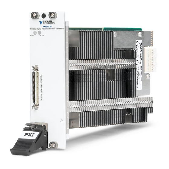
PXIe-6570
32-Channel Digital Pattern Instrument
This document lists the specifications for the PXIe-6570. When using the PXIe-6570 in the
Semiconductor Test System, refer to the Semiconductor Test System Specifications.
Specifications are subject to change without notice. Refer to
recent specifications.
NI defines the capabilities and performance of its Test & Measurement instruments as
Warranted specifications, Typical specifications, and Characteristics.
Warranted specifications describe the warranted, traceable product performance, including the
effects of temperature and uncertainty unless otherwise noted.
Typical specifications are unwarranted values that are representative of a majority of units,
including the effects of temperature and uncertainty unless otherwise noted.
Characteristics are unwarranted values that are relevant to the use of the product and convey
the expected performance of the product.
Specifications in this document are Characteristics unless otherwise noted. Specifications are
valid under the following conditions unless otherwise noted:
•
0 °C to 45 °C operating temperature.
•
Accuracy specifications are valid within ±5 ºC of the last self-calibration temperature.
•
The PXIe-6570 is within the 1 year recommended calibration interval.
•
The DUT Ground Sense (DGS) is the same potential as the Ground (GND) pins.
Note
158234C-
•
Chassis fans are set to the highest setting if the PXI Express chassis supports multiple
fans speeds.
•
Allow a 30 minute warm-up time.
Caution
documentation. Product misuse can result in a hazard. You can compromise the
safety protection built into the product if the product is damaged in any way. If the
product is damaged, return it to NI for repair.
The DGS feature is only available on PXIe-6570 module revisions
L or later.
xx
Do not operate the PXIe-6570 in a manner not specified in the user
ni.com/manuals
for the most
Advertisement
Table of Contents

Subscribe to Our Youtube Channel
Related Manuals for National Instruments PXIe-6570


Summary of Contents for National Instruments PXIe-6570
- Page 1 DEVICE SPECIFICATIONS PXIe-6570 32-Channel Digital Pattern Instrument This document lists the specifications for the PXIe-6570. When using the PXIe-6570 in the Semiconductor Test System, refer to the Semiconductor Test System Specifications. Specifications are subject to change without notice. Refer to ni.com/manuals...
-
Page 2: Table Of Contents
Note When the pin electronics on the PXIe-6570 are in the disconnect state, some I/O protection and sensing circuitry remain connected. Do not subject the PXIe-6570 to voltages beyond the supported measurement range. Contents General............................3 Timing............................3 Vector Timing........................3 Clock Generation...................... -
Page 3: General
The system channel count is the maximum number of channels available when using multiple PXIe-6570 instruments in a single chassis as a digital subsystem. Some functionality described in this document requires that a PXIe-6674T synchronization module be used in conjunction with each digital subsystem. -
Page 4: Drive And Compare Formats
• 0 — Drive zero. • 1 — Drive one. • L — Compare low. • H — Compare high. • X — Do not drive; mask compare. 4 | ni.com | PXIe-6570 Specifications... -
Page 5: Edge Timing
31 time sets can be configured. One additional time set, represented by a -, repeats the previous time set. For specifications across multiple instruments in a Semiconductor Test System, refer to the Semiconductor Test System Specifications. PXIe-6570 Specifications | © National Instruments | 5... -
Page 6: Driver, Comparator, Load
High Z, 50 Ω to V , Active Load TERM Leakage current <15 nA, in the High Z termination mode Active Load Programmable levels Commutating voltage (V Range -2 V to 6 V Resolution 122 µV 6 | ni.com | PXIe-6570 Specifications... -
Page 7: Ppmu
±2 µA 60 pA ±1% of range for Zone 1 of Figure 2. on page 8, warranted ±32 µA 980 pA ±128 μA 3.9 nA ±2 mA 60 nA ±32 mA 980 nA PXIe-6570 Specifications | © National Instruments | 7... -
Page 8: Ppmu Measure Current
Figure 3. on page 9, warranted ±32 μA 7.3 nA ±1.5% of range for Zone 2 of Figure 3. on page 9, warranted ±128 μA 30 nA ±2 mA 460 nA ±32 mA 7.3 μA 8 | ni.com | PXIe-6570 Specifications... -
Page 9: Ppmu Programmable Aperture Time
Figure 3. Warranted Current Accuracy Zones for PPMU Measure Current Zone 1 Zone 2 -100 -1.75 1.25 Voltage (V) PPMU Programmable Aperture Time Aperture time Minimum 4 μs Maximum 65 ms Resolution 4 μs PXIe-6570 Specifications | © National Instruments | 9... -
Page 10: Pattern Control
Refer to the following table for supported opcodes. Using matched and failed opcode parameters with multiple PXIe-6570 instruments requires the PXIe-6674T synchronization module. Other uses of flow-control opcodes with multiple PXIe-6570 instruments only require NI-TCLK synchronization. 10 | ni.com | PXIe-6570 Specifications... -
Page 11: Pipeline Latencies
• capture_stop • source_start • source Pipeline Latencies Minimum delay between 3 μs source_start opcode and the first opcode or source subsequent opcode source_start Matched and failed condition pipeline 80 cycles latency PXIe-6570 Specifications | © National Instruments | 11... -
Page 12: Source And Capture
To learn how to calculate achievable data rates for Digital Source or Digital Capture, visit ni.com/ info and enter the info code to access the Calculating DigitalSource DigitalCapture Digital Source Rate tutorial or the Calculating Digital Capture Rate tutorial. 12 | ni.com | PXIe-6570 Specifications... -
Page 13: Calibration Interval
Calculate the error if you override the PXIe-Clk100 timebase with the PXIe-6674T and increase the measurement time to 10 ms. Solution * 1, 000, 000 80� 20�� 1 − 80� 10�� − 100�� = 2��� Calibration Interval Recommended calibration interval 1 year PXIe-6570 Specifications | © National Instruments | 13... -
Page 14: Physical Characteristics
The PXIe-6570 draws current from a combination of the 3.3 V and 12 V power rails. The maximum current drawn from each of these rails can vary depending on the PXIe-6570 mode of operation. -
Page 15: Storage Environment
• IEC 61010-1, EN 61010-1 • UL 61010-1, CSA 61010-1 Note For UL and other safety certifications, refer to the product label or the Online Product Certification section. PXIe-6570 Specifications | © National Instruments | 15... -
Page 16: Electromagnetic Compatibility
NI recognizes that eliminating certain hazardous substances from our products is beneficial to the environment and to NI customers. For additional environmental information, refer to the Minimize Our Environmental Impact web page at ni.com/environment. This page contains the environmental regulations and 16 | ni.com | PXIe-6570 Specifications... - Page 17 NI products in your region, visit ni.com/environment/weee. 电子信息产品污染控制管理办法(中国 RoHS) National Instruments 符合中国电子信息产品中限制使用某些有害物 中国客户 质指令(RoHS)。关于 National Instruments 中国 RoHS 合规性信息,请登录 。(For information about China RoHS ni.com/environment/rohs_china compliance, go to ni.com/environment/rohs_china PXIe-6570 Specifications | © National Instruments | 17...
- Page 18 FAR 52.227-14, DFAR 252.227-7014, and DFAR 252.227-7015. © 2015—2017 National Instruments. All rights reserved. 375726D-01 June 27, 2017...
Need help?
Do you have a question about the PXIe-6570 and is the answer not in the manual?
Questions and answers