Table of Contents
Advertisement
Quick Links
USER GUIDE
FD-11613
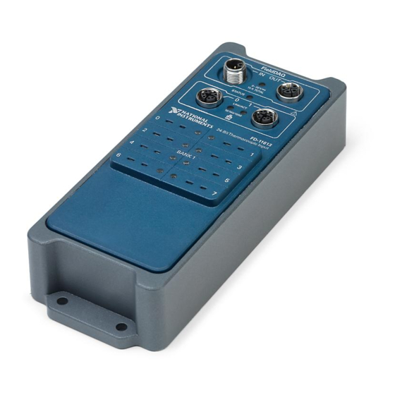
8-Channel Temperature Input Device for FieldDAQ
The FieldDAQ FD-11613 is an IP65/IP67-rated eight-channel thermocouple device that can be
networked and synchronized with IEEE 802.1AS devices. The FD-11613 supports B, E, J, K,
N, R, S, and T thermocouple types.
1. Power IN Connector
2. Power LED
3. Ethernet Port 0 and LED
4. Thermocouple Connectors and Open
Thermocouple LEDs
5. Mounting Holes
Figure 1. FD-11613 Front Panel
1
FieldDAQ
IN
2
STATUS
3
0
2
4
4
6
5
OUT
9-30 V
10 A TOTAL
0
1
LINK/ACT
10/100/1000
SYNC
FD-11613
24-Bit Thermocouple Input
1
3
5
7
6. Power OUT Connector
7. STATUS LED
8. Ethernet Port 1 and LED
9. SYNC Logo
™
5
6
7
8
9
TC–
TC+
Advertisement
Table of Contents

Subscribe to Our Youtube Channel
Related Manuals for National Instruments FD-11613


Summary of Contents for National Instruments FD-11613
- Page 1 8-Channel Temperature Input Device for FieldDAQ The FieldDAQ FD-11613 is an IP65/IP67-rated eight-channel thermocouple device that can be networked and synchronized with IEEE 802.1AS devices. The FD-11613 supports B, E, J, K, N, R, S, and T thermocouple types. Figure 1. FD-11613 Front Panel...
- Page 2 Mounting the Device Directly on a Flat Surface............35 Alternate Mounting Configurations................37 Firmware..........................37 Where to Go from Here......................37 Example Programs......................37 Related Documentation....................37 Training Courses......................40 Technical Support on the Web..................40 2 | ni.com | FD-11613 User Guide...
-
Page 3: Fd-11613 Basic Information
781094-01 M125F-Pigtail Power Cable (1 m, 2 m, 3 m lengths) 786172-01/02/03 M125F-M125M Power Cable (0.3 m, 1 m, 2 m lengths) 786173-0R3/01/02 FD-11940, Mini-TC Connector Protection Boot (Qty 8) 786394-01 FD-11613 User Guide | © National Instruments | 3... -
Page 4: Safety Guidelines
National Instruments for repair. The FD-11613 is rated for use in DRY or WET LOCATIONS. Hazardous voltages may not be connected to the device. A hazardous voltage is a voltage greater than 42.4 V peak voltage or 60 V DC in DRY LOCATIONS, and 22.6 V peak or 35 V DC in WET LOCATIONS. -
Page 5: Special Conditions For Marine Applications
EMC performance is attained. Unpacking The FD-11613 ships in an antistatic package to prevent electrostatic discharge (ESD). ESD can damage several components on the device. Notice Never touch the exposed pins of connectors. -
Page 6: What You Need To Get Started
8. B, E J, K, N, R, S, and/or T Thermocouples with Mini TC Connectors Note You can either use a shielded straight-through Ethernet cable or an Ethernet crossover cable to connect the FieldDAQ device directly to your computer. 6 | ni.com | FD-11613 User Guide... -
Page 7: Setting Up The Fielddaq Device
For information about wiring your external power source to the power connector, refer to Wiring External Power to the FieldDAQ Device. The FieldDAQ device requires an external power supply that meets the specifications listed in the FD-11613 Specifications. The Power LED lights. Refer to Power LED for information about Power LED status. - Page 8 If the device is not on your local subnet, right-click Network Devices and select Find Network NI-DAQmx Devices. In the Find Network NI-DAQmx Devices dialog box that opens, do one of the following: • Check the box that corresponds to your device in the Hostname column. 8 | ni.com | FD-11613 User Guide...
- Page 9 Enter the hostname of the device. The default hostname is FD11613-<serial number>. 10. Click Add Selected Devices. The FieldDAQ device icon changes from white to dark grey, indicating that it is recognized and present on the network. FD-11613 User Guide | © National Instruments | 9...
- Page 10 M12 connectors must be mated to cables or have caps installed on them to meet IP65/IP67 requirements. Cover the unused connectors with the included plastic caps whenever water, dust, or dirt are present. 10 | ni.com | FD-11613 User Guide...
-
Page 11: Power Connectors And Wiring
FD-11613 Basic Information. The FD-11613 has a maximum device power consumption of 4.9 W. Each FieldDAQ filters and regulates the supplied power for its tasks. When FieldDAQ devices are linked together through the power IN and power OUT connectors, the total current consumption of the chain equals the sum of every linked FieldDAQ device’s current consumption. -
Page 12: Power Connectors
Refer to the FD-11613 Specifications for information about the power connectors, power requirements, and current limits of your FieldDAQ device. Cap the power connectors when not in use. Power Connectors The following figure shows the pinout of the Power IN connector. -
Page 13: Thermocouple Connectors And Measurements
Refer to Power Requirements in the FD-11613 Specifications for information about the power supply input range. Refer to Safety Voltages in the FD-11613 Specifications for information about the maximum voltage from terminal to chassis ground. - Page 14 Open Thermocouple LED lights red. Refer to the Open Thermocouple Detection (OTD) topic in the NI-DAQmx Help for more information about how this feature is used in the NI-DAQmx API. 14 | ni.com | FD-11613 User Guide...
-
Page 15: Thermocouple Connectors
Filter, Differential Amplifier, and ADC—Each channel simultaneously passes through a filtered, differential amplifier before being sampled by a 24-bit ADC. The FieldDAQ device provides overvoltage protection for each channel; refer to the FD-11613 Specifications for more information about overvoltage protection. -
Page 16: Thermocouple Connection Guidelines
Connector Protection Boot (Qty 8) (NI part number 786394-01) on the mini-TC plugs. Make sure that devices you connect to the FD-11613 are compatible with the device specifications. Refer to your thermocouple documentation or the thermocouple wire spool to determine which wire is the positive lead and which wire is the negative lead. -
Page 17: Programming The Fielddaq Device
Temperature that you are measuring • Resistance of the thermocouple wires • Cold-junction temperature For the best accuracy performance, set up the FD-11613 according to Setting up the FieldDAQ Device Thermocouple Connection Guidelines to minimize thermal gradients across the terminals. -
Page 18: Time-Based Triggers
Sample Clock rate can run faster than the maximum rate for the device. When operating at a rate faster than the it can support, the FD-11613 returns the same point repeatedly, until a new conversion completes. In a hardware-timed task, the first point is acquired when the task is committed. -
Page 19: Timebases
Refer to the Time Triggering topic in the NI-DAQmx Help for more information on accessing time-based features in the NI-DAQmx API. Timebases The following figure shows the FD-11613 clock routing circuitry and timebases. Figure 13. Clock Routing Circuitry Onboard... -
Page 20: Synchronization Across A Network
NI Linux Real-Time controller, another FieldDAQ device, or any network connection on the same subnet. Refer to Topology Options for more information about using these ports in various topologies. 20 | ni.com | FD-11613 User Guide... -
Page 21: Ethernet Leds
Table 8. LED State/Device Status LED State Device Status Ethernet link Blinking, fast (12 blinks/s) Ethernet activity. Connected at 1,000 Mbit/s. Blinking, moderate (6 blinks/s) Ethernet activity. Connected at 100 Mbit/s. FD-11613 User Guide | © National Instruments | 21... -
Page 22: Internal Ethernet Switch
“BPDU guard”—enabled, the port connected to the FieldDAQ device is disabled and communication is lost. Refer to the documentation for your external switch for information about enabling RSTP and disabling BPDU guards on the switch. 22 | ni.com | FD-11613 User Guide... -
Page 23: Topology Options
Be aware that these devices will compete for network bandwidth with the FieldDAQ device. Reliable system design requires awareness of the bandwidth consumed by each device during operations. This topology offers no redundant links. FD-11613 User Guide | © National Instruments | 23... - Page 24 Node Node External Networking Switch Advantages: • Failure of any single Ethernet cable does not disrupt network communication • Additional nodes or heavier network traffic affects network performance less than the line topology 24 | ni.com | FD-11613 User Guide...
- Page 25 Unpowered nodes and/or node failure does not disrupt network communication with other nodes • Failure of any single Ethernet cable does not disrupt network communication when you have a redundant link FD-11613 User Guide | © National Instruments | 25...
-
Page 26: External Switch Requirements
When using an NI Real-Time controller as the host, you can only use select controllers with the NI Linux Real-Time operating system that support NI-DAQmx. Supported NI Linux Real-Time controllers include the IC-317x, cRIO-9035/9039 26 | ni.com | FD-11613 User Guide... - Page 27 For information about wiring your external power source to the power connector, refer to Wiring External Power to the FieldDAQ Device. The FieldDAQ device requires an external power supply that meets the specifications listed in the FD-11613 Specifications. The Power LED lights. Refer to Power LED for information about Power LED status.
- Page 28 12. Self-test your device in MAX by expanding Devices and Interfaces»Network Devices», right-clicking your FieldDAQ device, and selecting Self-Test. Self-test performs a brief test to determine successful device installation. When the self-test finishes, a message 28 | ni.com | FD-11613 User Guide...
-
Page 29: Troubleshooting Device Connectivity
When the FieldDAQ device is connected to a network, multiple users can access the device. To perform any DAQ functionality on the device, including reset and self-test, you must reserve the device in MAX. In MAX, an unreserved device or device reserved by another host FD-11613 User Guide | © National Instruments | 29... -
Page 30: Status Led
To reset your FieldDAQ device to factory-default settings, complete the following steps. Verify the power source is turned off. Connect Ethernet port 0 and port 1 with an Ethernet cable. Figure 20. Connecting Port 0 and Port 1 LINK/ACT 10/100/1000 SYNC 30 | ni.com | FD-11613 User Guide... -
Page 31: Mounting
75 °C or less. However, to ensure proper functionality during use above 75 °C, you must mount the FieldDAQ device in the reference mounting configuration shown in the following figure. Observe the following guidelines to mount the FieldDAQ device in the reference mounting configuration. FD-11613 User Guide | © National Instruments | 31... - Page 32 Before using any mounting methods, record the serial number from the back of the FieldDAQ device so that you can identify it in MAX. You will be unable to read the serial number after you mount the device. 32 | ni.com | FD-11613 User Guide...
-
Page 33: Mounting Requirements
10 A TOTAL STATUS 76.2 mm (3.00 in.) All Around LINK/ACT 10/100/1000 Cooling SYNC Dimensions Allow the appropriate space in front of the device for cabling clearance, as shown in the following figure. FD-11613 User Guide | © National Instruments | 33... - Page 34 38.7 mm 76.2 mm (1.50 in.) (3.00 in.) Measure the Measure the ambient ambient temperature temperature here here 25.4 mm 76.2 mm 76.2 mm 25.4 mm (1.00 in.) (3.00 in.) (3.00 in.) (1.00 in.) 34 | ni.com | FD-11613 User Guide...
-
Page 35: Dimensions
M5 or 10-32 panhead or sockethead cap screws appropriate for the surface. Complete the following steps to mount the FieldDAQ device directly on a flat surface. Prepare the surface for mounting the device using the surface mounting dimensions. FD-11613 User Guide | © National Instruments | 35... - Page 36 Fasten the device to the surface using the M5 or 10-32 screws. Tighten the screws to a maximum torque of 2.5 N · m (25.0 lb · in.). Figure 27. Fastening the Device to the Surface FieldDAQ 9-30 V 10 A TOTAL STATUS LINK/ACT 10/100/1000 SYNC 36 | ni.com | FD-11613 User Guide...
-
Page 37: Alternate Mounting Configurations
NI-DAQmx 17.6 or later. FieldDAQ The FD-11613 Quick Start, packaged with your device, describes how to install your NI-DAQmx for Windows software, how to set up your FieldDAQ device, and confirm that your device is operating properly. - Page 38 The FD-11613 Specifications lists all specifications for your FieldDAQ device. Go to ni.com/ manuals and search for FD-11613. The FD-11613 Safety, Environmental, and Regulatory Information, packaged with your device, includes important compliance precautions and connection information for your FieldDAQ device.
- Page 39 The NI-DAQmx Help contains API overviews and general information about measurement concepts. Select Start»All Programs»National Instruments»NI-DAQmx»NI-DAQmx Help. The NI-DAQmx C Reference Help describes the NI-DAQmx Library functions, which you can use with National Instruments data acquisition devices to develop instrumentation, acquisition, FD-11613 User Guide | © National Instruments | 39...
-
Page 40: Training Courses
NI trademarks. Other product and company names mentioned herein are trademarks or trade names of their respective companies. For patents covering NI products/technology, refer to the appropriate location: Help»Patents in your software, the file on your media, or the National Instruments Patent Notice at . You can find patents.txt ni.com/patents...
Need help?
Do you have a question about the FD-11613 and is the answer not in the manual?
Questions and answers