
Subscribe to Our Youtube Channel
Related Manuals for National Instruments PXI-5660


Summary of Contents for National Instruments PXI-5660
- Page 1 Computer-Based Instruments PXI-5660 RF Signal Analyzer User Manual PXI-5660 RF Signal Analyzer User Manual February 2002 Edition Part Number 323222C-01...
- Page 2 Switzerland 056 200 51 51, Taiwan 02 2528 7227, United Kingdom 01635 523545 For further support information, see the Technical Support and Professional Services appendix. To comment on the documentation, send email to techpubs@ni.com. © 2001–2002 National Instruments Corporation. All rights reserved.
- Page 3 Warranty The PXI-5660 RF Signal Analzer is warranted against defects in materials and workmanship for a period of one year from the date of shipment, as evidenced by receipts or other documentation. National Instruments will, at its option, repair or replace equipment that proves to be defective during the warranty period.
- Page 4 Classification requirements are the same for the Federal Communications Commission (FCC) and the Canadian Department of Communications (DOC). Changes or modifications not expressly approved by National Instruments could void the user’s authority to operate the equipment under the FCC Rules.
- Page 5 Canadian Department of Communications This Class B digital apparatus meets all requirements of the Canadian Interference-Causing Equipment Regulations. Cet appareil numérique de la classe B respecte toutes les exigences du Règlement sur le matériel brouilleur du Canada. Compliance to EU Directives Readers in the European Union (EU) must refer to the Manufacturer’s Declaration of Conformity (DoC) for information** pertaining to the CE Mark compliance scheme.
- Page 6 Conventions The following conventions are used in this guide: < > Angle brackets that contain numbers separated by an ellipsis represent a range of values associated with a bit or signal name—for example, DBIO<3..0>. » The » symbol leads you through nested menu items and dialog box options to a final action.
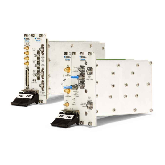
- Page 7 Radio Frequency—Though there is no precise definition, the term is often used for frequencies from tens of megahertz to several gigahertz. RFSA RF Signal Analyzer—In this document, RFSA refers to the PXI-5660, which consists of a PXI-5600 RF downconverter module and a PXI-5620 frequency-domain digitizer module.
-
Page 8: Table Of Contents
Distortion Limits of the RFSA ..............3-6 Choosing an Optimal Setting for the RFSA ............3-6 1 dB Gain Compression ....................3-7 Measurement Setup ..................3-7 Understanding RFSA Compression Limits .............3-8 Choosing the Optimal RFSA Attenuation Setting...........3-8 © National Instruments Corporation PXI-5660 RF Signal Analyzer User Manual... - Page 9 Hardware Overview Features.......................... 5-1 PXI-5600 Wideband RF Downconverter Module .......... 5-1 PXI-5620 IF Digitizer Module................ 5-2 Signal Paths ........................5-2 Block Diagrams ......................5-2 Calibration ........................5-4 Appendix A Technical Support and Professional Services PXI-5660 RF Signal Analyzer User Manual ni.com...
-
Page 10: Set Up And Configuration
Set Up and Configuration Required Equipment To set up and use the National Instruments PXI-5660 RF Signal Analyzer (RFSA), you need the following items: ❑ Both PXI-5660 RFSA modules: – PXI-5600 9 kHz to 2.7 GHz wideband RF downconverter module –... -
Page 11: Unpacking
Misuse of the product can result in a hazard. You can compromise the safety protection built into the product if the product is damaged in any way. If the product is damaged, return it to National Instruments for repair. PXI-5660 RF Signal Analyzer User Manual... - Page 12 Do not operate the product in an explosive atmosphere or where there may be flammable gases or fumes. Operate the product only at or below the pollution degree stated in the Specifications for the PXI-5660 RF Signal Analyzer Note to Users. Pollution is foreign matter in a solid, liquid, or gaseous state that can reduce dielectric strength or surface resistivity.
- Page 13 Installation category IV is for measurements performed at the source of the low-voltage (<1,000 V) installation. Examples of category IV are electric meters and measurements on primary overcurrent protection devices and ripple-control units. Below is a diagram of a sample installation. PXI-5660 RF Signal Analyzer User Manual ni.com...
-
Page 14: Installation
Chapter 1 Set Up and Configuration Installation The PXI-5660 RF Signal Analyzer consists of the following hardware modules and software components: ❑ NI-SCOPE and NI-TUNER drivers, contained on the included RF Signal Analyzer software CD ❑ NI Spectral Measurements Toolset CD ❑... -
Page 15: Software Installation
• Typical—this option installs required software components not present on your system and updates past installations of NI software to work with the PXI-5660 RF Signal Analyzer. • Complete—this option installs all RF Signal Analyzer software components and overwrites old installations. Use this option for highest performance or if you are unsure of which software components you need. - Page 16 Note To use the included rigid coaxial cables, you must install the PXI-5620 digitizer module in the PXI slot immediately to the right of the PXI-5600 downconverter module. © National Instruments Corporation PXI-5660 RF Signal Analyzer User Manual...
- Page 17 Chapter 1 Set Up and Configuration Tighten the two screws on the frequency-domain digitizer module front panel. PXI Chassis Your PXI-5620 Ejector Handle in Down Position Figure 1-3. PXI-5620 Frequency-Domain Digitizer Module Installation PXI-5660 RF Signal Analyzer User Manual ni.com...
-
Page 18: The Rfsa Front Panels
The lower LED indicates when the downconverter module internal oscillators are phase-locked. Refer to Table 1-1 for explanations of the connectors and their uses. All inputs and outputs are AC coupled. Table 1-1. PXI-5660 RF Signal Analyzer Front Panel Connectors Front Panel Connector PXI-5600 RF... -
Page 19: The Pxi-5600 Internal Timebase And The Pxi Backplane Clock
10 MHz OUT connector and the PXI 10 MHz I/O connector on the PXI-5600 downconverter module front panel. Refer to Table 1-2 for more information about timing configurations and front panel connections. PXI-5660 RF Signal Analyzer User Manual 1-10 ni.com... - Page 20 RF DOWNCONVERTER 64 MS/s Digitizer INPUT REF CLK IN POWER PFI 1 +20 dBm MAX +30 dBm MAX STATUS WITH ATTN TTL (+5 V MAX) Figure 1-4. Front Panel Connections © National Instruments Corporation 1-11 PXI-5660 RF Signal Analyzer User Manual...
- Page 21 Note RF downconverter module as separate units, remove the relevant front panel connections. However, you may wish to lock the digitizer module to the downconverter module or other references when acquiring data. PXI-5660 RF Signal Analyzer User Manual 1-12 ni.com...
-
Page 22: Configuring The Hardware Modules In Max
Set Up and Configuration Configuring the Hardware Modules in MAX Launch Measurement & Automation Explorer (MAX) by double-clicking the desktop icon or by selecting Start»Programs»National Instruments» Measurement & Automation. MAX automatically detects new installed devices. Double-click Devices and Interfaces to see a list of recognized devices. If the PXI-5620 digitizer module and the PXI-5600 downconverter module do not automatically appear, refresh the list by pressing <F5>. -
Page 23: Spectral Measurements Toolset Basics
Set Up and Configuration Spectral Measurements Toolset Basics The NI Spectral Measurements Toolset (SMT) is the measurement and analysis software for your PXI-5660 RF Signal Analyzer. This software package allows easy configuration of spectral measurements and supports a variety of operations, including: •... -
Page 24: Making Basic Measurements
The interactive RF Signal Analyzer Example VI demonstrates these measurement capabilities of the RFSA. The RF Signal Analyzer Example VI is located at Start»Programs»National Instruments»RF Signal Analyzer»RF Signal Analyzer Example VI. When the VI is running, press <Ctrl-H> to view information about the controls. -
Page 25: Resolving Two Signals Closely Spaced In Frequency
Using a large resolution bandwidth setting, two closely spaced signals of equal amplitude appear as one signal in the displayed spectrum. To resolve these two signals, decrease the RFSA resolution bandwidth setting. PXI-5660 RF Signal Analyzer User Manual ni.com... - Page 26 Use the increment/decrement arrows to select views and change control settings. Select the RF Settings view of the Hardware Settings menu. Set the center frequency to MHz, the span to MHz, and the resolution bandwidth to kHz. © National Instruments Corporation PXI-5660 RF Signal Analyzer User Manual...
-
Page 27: Measuring Harmonics
On the PXI-5600 downconverter front panel, connect one of the 10 MHz OUT reference outputs to the INPUT connector. Open the RF Signal Analyzer Example VI by selecting Start» Programs»National Instruments»RF Signal Analyzer»RF Signal Analyzer Example VI. PXI-5660 RF Signal Analyzer User Manual ni.com... - Page 28 In the Peak Search Setting submenu of the Peak Search view, select Multiple Peaks. Click the Select Peak button. Select the harmonic peak to read off its value to the fourth harmonic. © National Instruments Corporation PXI-5660 RF Signal Analyzer User Manual...
-
Page 29: Measuring Adjacent Channel Power
Set the averaging controls located below the spectrum graph to the following values: • averaging type—rms averaging • weighting type—linear • size— averages • linear weighting mode—moving average In the Units control below the spectrum graph, select dBm. PXI-5660 RF Signal Analyzer User Manual ni.com... - Page 30 Three graphical histogram bars appear on the spectrum graph. The center bar shows the total power in the 10 kHz bandwidth channel. The two bars on each side show the upper and lower adjacent channel powers. © National Instruments Corporation PXI-5660 RF Signal Analyzer User Manual...
-
Page 31: Guidelines For Making Accurate Measurements
Amplitude dynamic range is the difference between the maximum input level of a device and its minimum detectable signal level. This value estimates the ability of the PXI-5660 RFSA to distinguish and measure the amplitude difference of two signals. The RFSA can make signal measurements over a wide frequency range—from 9 kHz to... -
Page 32: Harmonic Distortion
This setup injects a very clean sinusoidal signal into the unit under test (UUT). Any harmonic content at the UUT output is assumed to be generated by the UUT instead of the source. PXI-5660 RF Signal Analyzer User Manual ni.com... -
Page 33: Understanding The Rfsa Harmonic Distortion Limits
Understanding the RFSA Harmonic Distortion Limits As with all signal analyzers, there are residual distortions inherent in the PXI-5660 RFSA. It is important that these distortions do not corrupt your measurement. The level of internal distortion is a function of the linearity of the system, which is primarily determined at the input mixer. -
Page 34: Choosing An Optimal Setting For The Rfsa
− where refers to the output of the UUT, P is the power level of one of the output third-order products, and P is the power level of one of the fundamental tones. PXI-5660 RF Signal Analyzer User Manual ni.com... -
Page 35: Measurement Setup
Use the IIP specification of the PXI-5660 RFSA as a guide to optimize its settings when measuring the IMD of an external device. The two tones injected into the UUT must be free from any third-order products. -
Page 36: Understanding Two-Tone Third-Order Intermodulation Distortion Limits Of The Rfsa
Tune to the third-order distortion product frequency of interest, either F − F − . Then decrease the resolution bandwidth until a distortion spur appears. Increase the attenuation level. PXI-5660 RF Signal Analyzer User Manual ni.com... -
Page 37: Db Gain Compression
Measurement Setup Measuring the 1 dB gain compression point of a device requires driving the UUT into compression without driving the PXI-5660 RFSA into compression. This requires proper attenuation at the RFSA and a signal source of sufficient power to compress the UUT. You may apply attenuation by programming the internal input attenuators or using external attenuation. -
Page 38: Understanding Rfsa Compression Limits
–12 dBm in this case. Understanding RFSA Compression Limits Like all signal analysis devices, the PXI-5660 RF Signal Analyzer is not completely linear and will eventually reach compression. However, the RF Signal Analyzer architecture possesses a high degree of linearity, and the RFSA compression point is typically 5 dBm or higher. -
Page 39: Noise Figure
------------- - where G is the power gain of the UUT, k ≈ 1.38 × 10 –23 is Boltzmann’s ≈ 290 constant, and T K is the room temperature. © National Instruments Corporation PXI-5660 RF Signal Analyzer User Manual... -
Page 40: Measurement Setup
Chapter 3 Guidelines for Making Accurate Measurements If you use the PXI-5660 RF Signal Analyzer to measure the output noise of a UUT, the result of the measurement contains not only UUT noise but also noise intrinsic to the PXI-5660. If the UUT gain (G) is known, compute the noise figure of the UUT with the following equation: ... - Page 41 UUT noise figure: • The value from step 6 equals N rfsa • The value from step 10 equals G • The value from step 12 equals N © National Instruments Corporation 3-11 PXI-5660 RF Signal Analyzer User Manual...
-
Page 42: Troubleshooting
• Ensure that the external source signal is large enough—typically greater than –10 dBm If you programmed the PXI-5660 RFSA to use the PXI-5600 downconverter module internal timebase, check for the following errors: • If the RFSA measures the frequency incorrectly or shows no signal when one is supplied, one or more of the local oscillators is not phase-locked. -
Page 43: The Digitizer Module Does Not Phase Lock To The Downconverter Module
2 GHz. Unless you are using high-quality cables, expect losses when working with high-frequency signals. • Ensure that you are using the amplitude calibration functions in the SMT. Failure to apply calibration functions results in large amplitude errors. PXI-5660 RF Signal Analyzer User Manual ni.com... -
Page 44: Rfsa Frequency Reading Does Not Match Source
• Check that the PXI-5620 digitizer module is phase-locked to the PXI-5600 downconverter module, either through the front panel SMA connectors or the PXI backplane. © National Instruments Corporation PXI-5660 RF Signal Analyzer User Manual... -
Page 45: Hardware Overview
PXI-5660 RFSA hardware, including brief explanations of hardware features and signal paths, and block diagrams of each module. Features The PXI-5660 RF Signal Analyzer consists of the PXI-5600 wideband downconverter module, and the PXI-5620 RF digitizer module. PXI-5600 Wideband RF Downconverter Module... -
Page 46: Pxi-5620 If Digitizer Module
The PXI-5620 filters and conditions the signal. Gain and dither are applied. The ADC converts the signal from analog to digital. The data is sent to onboard memory (the buffer). The data is transferred to your host computer. Block Diagrams PXI-5660 RF Signal Analyzer User Manual ni.com... - Page 47 Chapter 5 Hardware Overview Figure 5-1. PXI-5600 RF Downconverter Module Block Diagram © National Instruments Corporation PXI-5660 RF Signal Analyzer User Manual...
-
Page 48: Calibration
To guarantee specified accuracy, NI recommends returning both modules of your PXI-5660 RFSA to the factory for annual recalibration. The PXI-5600 and PXI 5620 modules are calibrated independently of one another, not as a combined system. At this time, recalibration of both modules can only be performed at NI. -
Page 49: Technical Support And Professional Services
Technical Support and Professional Services Visit the following sections of the National Instruments Web site at for technical support and professional services: ni.com • Support—Online technical support resources include the following: – Self-Help Resources—For immediate answers and solutions, visit our extensive library of technical support resources available in English, Japanese, and Spanish at .
Need help?
Do you have a question about the PXI-5660 and is the answer not in the manual?
Questions and answers