National Instruments NI PXI-6551 Getting Started Manual
Digital waveform generator/ analyzer
Hide thumbs
Also See for NI PXI-6551:
- Getting started manual (40 pages) ,
- Getting started manual (24 pages) ,
- Getting started manual (32 pages)
Table of Contents
Advertisement
Quick Links
GETTING STARTED GUIDE
NI Digital Waveform
Generator/Analyzer
For NI PXI-6551/6552 Modules
This document explains how to install, configure, test and set up a National
Instruments digital waveform generator/analyzer. This document applies
specifically to the NI PXI-6551/6552 (NI 655X) modules. For more
information on the NI 655X, such as features and programming, refer to the
NI Digital Waveform Generator/Analyzer Help at Start»Programs»
National Instruments»NI-HSDIO» Documentation»NI Digital
Waveform Generator/Analyzer Help.
Refer to the specifications document that ships with your module for detailed
specifications.
For free downloads of the most current versions of product documentation
and example programs, visit
Contents
Conventions ...............................................................................................2
Step 1. Unpack the Hardware ....................................................................3
Step 2. Verify the Components..................................................................3
Optional Equipment and Software.....................................................4
Documentation...................................................................................4
Step 3. Install the Software ........................................................................5
Choose and Install Your ADE ...........................................................5
Install NI-HSDIO...............................................................................5
(Optional) Install the NI Digital Waveform Editor ...........................6
Step 4. Install the Module ..........................................................................6
Procedure 1: Installing the Module in a PXI Chassis ........................6
Step 5. Configure the Module....................................................................9
Step 6. Use the Test Panel to Generate and Acquire Data.........................10
July 2003
323308A-01
ni.com/instruments
.
Advertisement
Table of Contents

Subscribe to Our Youtube Channel
Related Manuals for National Instruments NI PXI-6551


Summary of Contents for National Instruments NI PXI-6551
-
Page 1: Table Of Contents
This document explains how to install, configure, test and set up a National Instruments digital waveform generator/analyzer. This document applies specifically to the NI PXI-6551/6552 (NI 655X) modules. For more information on the NI 655X, such as features and programming, refer to the NI Digital Waveform Generator/Analyzer Help at Start»Programs»... -
Page 2: Conventions
Step 7. Connect Signals to the Front Panel..........11 Connecting Cables and Accessories ..........14 Wiring for Common Measurements ..........15 Step 8. Program the Module Using NI-HSDIO .........16 Safety and Compliance Information ............16 FCC/Canada Radio Frequency Interference Compliance....16 Safety Information ................18 Conventions The following conventions are used in this guide: <>... -
Page 3: Step 1. Unpack The Hardware
Store the module in the antistatic package when the module is not in use. Step 2. Verify the Components Make sure you have the following items: ❑ NI 655X digital waveform generator/analyzer ❑ NI-HSDIO (High-Speed Digital I/O) driver software CD © National Instruments Corporation NI Digital Waveform Generator/Analyzer Guide... -
Page 4: Optional Equipment And Software
❑ The documentation included with the digital waveform generator/analyzer and driver software. Refer to the Documentation section for a listing of the documentation you may have. ❑ PXI/CompactPCI chassis and controller ❑ Phillips screwdriver ❑ One of the following application development environment (ADE) software packages and documentation: –... -
Page 5: Step 3. Install The Software
2. Follow the instructions in the installation prompts. For troubleshooting and operating system-specific instructions, refer to the Hardware Installation Wizard at ni.com/support/install If you are running Windows 2000/NT 4.0/XP, you must have Note administrator access to perform the installation. © National Instruments Corporation NI Digital Waveform Generator/Analyzer Guide... -
Page 6: (Optional) Install The Ni Digital Waveform Editor
NI Script Editor The NI Script Editor is included on the NI-HSDIO CD and is installed when you install the driver. The NI Script Editor provides an intuitive interface to aid you in developing linking and looping pattern generation operations. The NI Script Editor Help contains more information about the NI Script Editor. -
Page 7: Procedure 2: Installing The Module In A Compactpci Chassis
The procedure for installing the module in a CompactPCI chassis is the same as the procedure for installing the module in a PXI chassis, but the following additional considerations apply to using your PXI module with a CompactPCI chassis. © National Instruments Corporation NI Digital Waveform Generator/Analyzer Guide... - Page 8 • The CompactPCI specification permits vendors to develop sub-buses that coexist with the basic PCI interface on the CompactPCI bus. Compatible operation of NI PXI modules is not guaranteed between CompactPCI devices with different sub-buses nor between CompactPCI devices with sub-buses from different vendors and PXI.
-
Page 9: Step 5. Configure The Module
If an error occurred, refer to ni.com/support for troubleshooting information. 6. Record the device name assigned to the digital device. You will use this information when you program the module. © National Instruments Corporation NI Digital Waveform Generator/Analyzer Guide... -
Page 10: Step 6. Use The Test Panel To Generate And Acquire Data
Step 6. Use the Test Panel to Generate and Acquire Data To verify your module configuration, use the device test panel in MAX to generate and acquire simple digital data using your module. To generate digital data, complete the following steps: 1. -
Page 11: Step 7. Connect Signals To The Front Panel
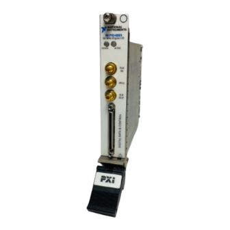
SMB jacks (CLK IN, PFI 0, and CLK OUT) and one 68-pin VHDCI connector (Digital Data & Control, or DDC). The connectors and their functions are described in Tables 1 and 2. © National Instruments Corporation NI Digital Waveform Generator/Analyzer Guide... - Page 12 RESERVED RESERVED RESERVED RESERVED NI PXI-6551 RESERVED RESERVED 50 MHz Digital I/O RESERVED RESERVED ACCESS ACTIVE RESERVED RESERVED RESERVED RESERVED RESERVED DIO 19 DIO 18 PFI 0 DIO 17 DIO 16 DIO 15 DIO 14 RESERVED DIO 13 DIO 12...
- Page 13 62, 66 1, 3, 5, 7, 8, 9, RESERVED N/A These terminals are reserved for future 11, 35, 37, 39, use. Do not connect to these pins. 41, 43, 45, 52, © National Instruments Corporation NI Digital Waveform Generator/Analyzer Guide...
-
Page 14: Connecting Cables And Accessories
NI CB-2162, refer to the NI CB-2162 User Guide. Figure 4 shows how to connect the NI digital waveform generator/analyzer and the NI CB-2162 using the NI SHC68-C68-D2 cable assembly. NI PXI-1042 NI PXI-6551 50 MHz Digital I/O ACCESS ACTIVE PFI 0... -
Page 15: Wiring For Common Measurements
Use NI-HSDIO to set the input impedance of the NI 655X to 10 k or 50 depending on your application. Refer to the NI Digital Waveform Generator/Analyzer Help for more information about signal termination. © National Instruments Corporation NI Digital Waveform Generator/Analyzer Guide... -
Page 16: Step 8. Program The Module Using Ni-Hsdio
These classes are known as Class A (for use in industrial-commercial locations only) or Class B (for use in residential or commercial locations). All National Instruments (NI) products are FCC Class A products. Depending on where it is operated, this Class A product could be subject to restrictions in the FCC rules. - Page 17 The CE marking Declaration of Conformity contains important supplementary information and instructions for the user or installer. The CE marking Declaration of Conformity contains important supplementary information and instructions for the user or installer. © National Instruments Corporation NI Digital Waveform Generator/Analyzer Guide...
-
Page 18: Safety Information
Misuse of the product can result in a hazard. You can compromise the safety protection built into the product if the product is damaged in any way. If the product is damaged, return it to National Instruments for repair. Do not substitute parts or modify the product except as described in this document. - Page 19 Working voltage is the highest rms value of an AC or DC voltage that can occur across any particular insulation. MAINS is defined as a hazardous live electrical supply system that powers equipment. Suitably rated measuring circuits may be connected to the MAINS for measuring purposes. © National Instruments Corporation NI Digital Waveform Generator/Analyzer Guide...
- Page 20 CVI™, LabVIEW™, National Instruments™, NI™, and ni.com™ are trademarks of National Instruments Corporation. Product and company names mentioned herein are trademarks or trade names of their respective companies. For patents covering National Instruments products, refer to the appropriate location: Help»Patents in your software, the patents.txt file on your CD, or ni.com/patents .
Need help?
Do you have a question about the NI PXI-6551 and is the answer not in the manual?
Questions and answers