Table of Contents
Advertisement
Quick Links
GETTING STARTED GUIDE
PXIe-5668
Up to 26.5 GHz PXI Vector Signal Analyzer
Note
Before you begin, install and configure your chassis and controller.
This document explains how to install, configure, and test the PXIe-5668. The PXIe-5668 is a
26.5 GHz or 14 GHz modular vector signal analyzer (VSA). The PXIe-5668 ships with the
NI-RFSA instrument driver, which you use to program the device. You can also use NI-RFmx,
available at ni.com/downloads, to program the device.
The PXIe-5668 comprises the following devices:
•
PXIe-5606 RF Signal Downconverter (PXIe-5606) RF downconverter
•
PXIe-5624 IF Digitizer (PXIe-5624) intermediate frequency (IF) digitizer
•
PXIe-5653 RF Analog Signal Generator (PXIe-5653) synthesizer/local oscillator (LO)
source module
In this document, PXIe-5668 refers to both the PXIe-5668 26.5 GHz VSA and the PXIe-5668
14 GHz VSA unless otherwise specified.
Caution
manner not described in this document.
Hot Surface
temperatures and cause burns. Allow the PXIe-5668 to cool before removing it from
the chassis.
Contents
Electromagnetic Compatibility Guidelines............................................................................... 2
Verifying the System Requirements..........................................................................................2
Unpacking the Kit..................................................................................................................... 2
Verifying the Kit Contents................................................................................................ 4
Preparing the Environment....................................................................................................... 5
Choosing and Installing the Software....................................................................................... 5
Software Options...............................................................................................................5
Installing the Software...................................................................................................... 6
Installing the PXIe-5668........................................................................................................... 7
Interconnecting the PXIe-5668 Modules.......................................................................... 8
Configuring the PXIe-5668 in MAX...................................................................................... 22
The protection provided by this product may be impaired if it is used in a
If the PXIe-5668 has been in use, it may exceed safe handling
Advertisement
Table of Contents

Related Manuals for National Instruments PXIe-5668


Summary of Contents for National Instruments PXIe-5668
-
Page 1: Table Of Contents
Before you begin, install and configure your chassis and controller. This document explains how to install, configure, and test the PXIe-5668. The PXIe-5668 is a 26.5 GHz or 14 GHz modular vector signal analyzer (VSA). The PXIe-5668 ships with the NI-RFSA instrument driver, which you use to program the device. -
Page 2: Electromagnetic Compatibility Guidelines
1 meter in length. Verifying the System Requirements To use the PXIe-5668, your system must meet certain requirements. For more information about minimum system requirements, recommended system, and supported application development environments (ADEs), refer to the readme, which is installed or available at ni.com/manuals. - Page 3 Do not install a device if it appears damaged in any way. Unpack any other items and documentation from the kit. Store the device in the antistatic package when the device is not in use. PXIe-5668 Getting Started Guide | © National Instruments | 3...
-
Page 4: Verifying The Kit Contents
Verifying the Kit Contents Figure 1. PXIe-5668 Kit Contents and Replacement Part Numbers 1. PXIe-5624 IF Digitizer Module 9. SMA Driver Bit, Part Number 190487B-01 2. PXIe-5606 RF Downconverter Module 10. RF Torque Screwdriver, Part Number 780487-01 3. PXIe-5653 Synthesizer/LO Source Module 11. -
Page 5: Preparing The Environment
Other Equipment There are several required items not included in your device kit that you need to operate the PXIe-5668. Your application may require additional items not included in your kit to install or operate your device. • A PXI Express chassis and chassis documentation. The PXIe-1085 chassis is one available option for your device. -
Page 6: Installing The Software
Windows users may see access and security messages during installation. Accept the prompts to complete the installation. When the installer completes, select Restart in the dialog box that prompts you to restart, shut down, or restart later. 6 | ni.com | PXIe-5668 Getting Started Guide... -
Page 7: Installing The Pxie-5668
5. PXI Express Peripheral Slot 3. PXI Express Hybrid Peripheral Slot PXIe-5668 modules can be placed in PXI Express peripheral slots, PXI Express hybrid peripheral slots, or PXI Express system timing slots. Touch any metal part of the chassis to discharge static electricity. -
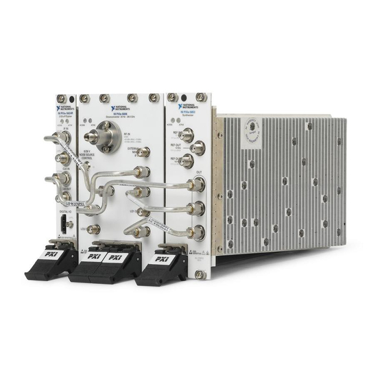
Page 8: Interconnecting The Pxie-5668 Modules
Installing the Software on page 6 Interconnecting the PXIe-5668 Modules Complete the following steps to interconnect the PXIe-5668 front panel connectors, as shown in the following figure. Notice The signal pins of this product's input/output ports can be damaged if subjected to ESD. - Page 9 Figure 4. Installation of the PXIe-5668 Cables and 50 Ω Loads ACCESS ACTIVE 1. SMA-to-SMA Cable, Labeled V 4. SMA-to-SMA Cable, Labeled Y 2. SMA-to-SMA Cable, Labeled U 5. SMA-to-SMA Cable, Labeled X 3. 50 Ω Load 6. SMA-to-SMA Cable, Labeled W...
- Page 10 If you are using an active device, such as a preamplifier or switch routed to the PXIe-5606 RF IN connector, ensure that the device cannot generate signal transients greater than the RF and DC specifications of the PXIe-5606 RF IN connector. 10 | ni.com | PXIe-5668 Getting Started Guide...
- Page 11 PXIe-5606 RF Downconverter Module The PXIe-5606 RF downconverter module front panel contains eight connectors and two LEDs. Figure 5. PXIe-5606 Front Panel PXIe-5668 Getting Started Guide | © National Instruments | 11...
- Page 12 Connects to the LO3 OUT connector on the PXIe-5653 module front panel. This connector is the input terminal for the LO3 (800 MHz) source. LO3 IN is an SMA connector with an impedance of 50 Ω (nominal). 12 | ni.com | PXIe-5668 Getting Started Guide...
- Page 13 LO2 OUT is disabled by default. LO2 OUT is an SMA connector with an impedance of 50 Ω (nominal). Note When part of a PXIe-5668, LO2 OUT is disabled except when connected to the PXIe-5624 CLK IN. LO3 OUT Output terminal for the LO3 (800 MHz) source.
- Page 14 You can order the DC block separately as a spare or replacement part. The part number is 787672-01. Refer to the following sections for instructions on how to remove and reinstall the DC block. 14 | ni.com | PXIe-5668 Getting Started Guide...
- Page 15 Remove the two screws on the DC block support with a Torx screwdriver with a T8 bit. Loosen the DC block support with a wrench and remove. Loosen and remove the DC block from the RF IN connector with a torque wrench. PXIe-5668 Getting Started Guide | © National Instruments | 15...
- Page 16 Insert two screws through the DC block support mounting holes into the holes on the PXIe-5606 as shown in the figure above. Tighten the screws with a Torx screwdriver with a T8 bit to a torque of 1.65 N · m (5 lb · in.). 16 | ni.com | PXIe-5668 Getting Started Guide...
- Page 17 The signal pins of this product's input/output ports can be damaged if subjected to ESD. To prevent damage, turn off power to the product before connecting cables and employ industry-standard ESD prevention measures during installation, maintenance, and operation. PXIe-5668 Getting Started Guide | © National Instruments | 17...
- Page 18 IF IN is an SMA connector with a nominal input impedance of 50 Ω. When used in a PXIe-5668 the IF IN connector has a +6 dBm full-scale input level and a -6 dBm nominal input level. The IF IN connector damage level is +20 dBm.
- Page 19 RED—The module has detected an error. NI-RFSA must access the module to determine the cause of the error. The LED remains red until the error condition is removed. PXIe-5668 Getting Started Guide | © National Instruments | 19...
- Page 20 5 V p-p MAX REF OUT 10 MHz 1.5 V p-p MAX REF OUT 100 MHz 1.5 V p-p MAX 800 MHz 4 GHz 3.2 GHz - 8.3 GHz SENSITIVE ALL PORTS 50 Ω 20 | ni.com | PXIe-5668 Getting Started Guide...
- Page 21 Connects to the LO3 IN connector on the PXIe-5606 module front panel. This connector is the output terminal for the LO3 (800 MHz) source. LO3 OUT is an SMA connector with an impedance of 50 Ω (nominal). PXIe-5668 Getting Started Guide | © National Instruments | 21...
-
Page 22: Configuring The Pxie-5668 In Max
In the configuration tree, expand Devices and Interfaces to see the list of installed NI hardware. Note If you are using the PXIe-5668 with the LabVIEW Real-Time Module, expand Remote Systems. Find your target IP address or name, expand it, and then expand Devices and Interfaces. -
Page 23: Self-Calibration
In the Associated Devices section, select the appropriate module from each system component drop-down listbox. For the PXIe-5668, you must associate the PXIe-5624 IF digitizer module and the PXIe-5653 LO source module with the PXIe-5606 RF downconverter. Click Save in the MAX toolbar. -
Page 24: Performing A Device Self-Calibration Using The Ni-Rfsa Sfp
Table 12. Locations of NI-RFmx Software Location LabVIEW Available on the LabVIEW Functions palette at Measurement I/O»NI-RFmx. LabWindows/CVI NI-RFmx functions are available from the LabWindows/CVI Library menu at Library»RFmx SpecAn Library and Library» RFmx Demod Library. 24 | ni.com | PXIe-5668 Getting Started Guide... - Page 25 Windows 10 (32-bit)/8.1 (32-bit)/7 (32-bit)— Program Files\National Instruments • Windows 10 (64-bit)/8.1 (64-bit)/7 (64-bit)— Program Files (x86)\National Instruments Microsoft .NET For the location of .NET class libraries, refer to the installed NI-RFmx readme. PXIe-5668 Getting Started Guide | © National Instruments | 25...
- Page 26 — Program Files (x86)\IVI Foundation\IVI Microsoft .NET To use the .NET API, you must install the .NET class libraries. For download and installed file locations, visit ni.com/info and enter Info Code NETAPIdriversupport 26 | ni.com | PXIe-5668 Getting Started Guide...
-
Page 27: Programming Examples Locations
NI Example Finder to locate programming examples. Launch LabVIEW or LabWindows/CVI. Select Help»Find Examples to open the NI Example Finder. Navigate to Hardware Input and Output»Modular Instruments. Open the example that best matches your application requirements. PXIe-5668 Getting Started Guide | © National Instruments | 27... -
Page 28: Troubleshooting
<NIDocDir> directory. \National Instruments Note LabVIEW examples that demonstrate integration of the PXIe-5668 with NI RF vector signal generators and NI toolkit software, including the NI Modulation Toolkit, are also available online at ni.com/examples. Troubleshooting If an issue persists after you complete a troubleshooting procedure, contact NI technical support or visit ni.com/support. -
Page 29: Configuration
What Should I Do if the Device Does Not Initialize? Failure to initialize may indicate a problem with module interconnections or with MAX. If the niRFSA Initialize VI or the niRFSA_init function returns an error and the PXIe-5668 fails to initialize, complete the following steps:... - Page 30 Reconnect the PXIe-5668 hardware module front panel cables securely. Power on your system and run the MAX configuration and self-test procedures. Related Information Interconnecting the PXIe-5668 Modules on page 8 Configuring the PXIe-5668 in MAX on page 22 What Should I Do if the PXIe-5624 IF Digitizer Module Does Not...
-
Page 31: Measurements
What Should I Do if the Device Amplitude Reading Does Not Match the Source? Verify that the discrepancy between the PXIe-5668 and the source is within the error limits of the devices. Verify the absolute amplitude accuracy of the PXIe-5668 using the appropriate value. -
Page 32: Where To Go Next
NI Application Engineers. Visit ni.com/services for information about the services NI offers. Visit ni.com/register to register your NI product. Product registration facilitates technical support and ensures that you receive important information updates from NI. 32 | ni.com | PXIe-5668 Getting Started Guide... - Page 33 NI corporate headquarters is located at 11500 North Mopac Expressway, Austin, Texas, 78759-3504, USA. For up-to-date contact information for your location, visit ni.com/contact. PXIe-5668 Getting Started Guide | © National Instruments | 33...
- Page 34 NI trademarks. Other product and company names mentioned herein are trademarks or trade names of their respective companies. For patents covering NI products/technology, refer to the appropriate location: Help»Patents in your software, the file on your media, or the National Instruments Patent Notice at . You can find patents.txt ni.com/patents...
Need help?
Do you have a question about the PXIe-5668 and is the answer not in the manual?
Questions and answers