Table of Contents
Advertisement
Quick Links
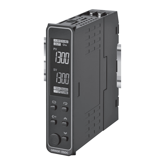
Digital Temperature Controller
E5DC
The E5DC Mounts to DIN Track and Is Ideal
for Connections to HMIs and PLCs.
It provides the Same Easy Operation and
Advanced Performance as the Rest of the
E5@C Series.
• A slim body at 85 × 22.5 mm (D × W) that fits into narrow control
panels and mounts to DIN Track.
• Removable terminal block for easy replacement to simplify maintenance.
• High-speed sampling at 50 ms for applications with high-speed
temperature increases.
• Easy connections to a PLC with programless communications.
• Set up the Controller without wiring the power supply by connecting
to the computer with a Communications Conversion Cable (sold separately).
Setup is easy with the CX-Thermo (sold separately).
• Models are available with up to 2 auxiliary outputs and 1 event input to
complete basic functions.
• A white PV display (height: 8.5 mm) is easy to read when setting up,
checking alarms, and making settings in a control panel.
Main I/O Functions
Sensor Input
Universal input
• Thermocouple
• Pt
• Analog current/voltage
Indication Accuracy
• Thermocouple input:
±0.3% of PV
• Pt input: ±0.2% of PV
• Analog input:
±0.2% of FS
Sampling Period
• 50 ms
Event Inputs
• None
• 1
Serial Communications
• None
• RS-485
This datasheet is provided as a guideline for selecting products.
Be sure to refer to the following manuals for application precautions and other information required for operation before attempting
to use the product.
E5@C Digital Temperature Controllers User's Manual (Cat. No. H174)
E5@C Digital Temperature Controllers Communications Manual (Cat. No. H175)
(22.5 mm Wide, and DIN Track-mounting Type)
• PF (shift) Key
• Temperature status display
• Simple programming
• Independent heating and
cooling PID control
• Changed parameter display
• Display brightness setting
Refer to your OMRON website for the most recent
information on applicable safety standards.
E5DC
22.5 mm Wide, and
DIN Track-mounting Type
E5DC
Refer to Safety Precautions on page 54.
Dual displays: PV/SV
4-digit displays
Control Output 1
• Relay output
• Voltage output (for driving SSR)
• Linear current output
Auxiliary Outputs
• None
• 2
1
Advertisement
Table of Contents

Related Manuals for Omron E5DC-RX2ASM-000


Summary of Contents for Omron E5DC-RX2ASM-000
- Page 1 • Models are available with up to 2 auxiliary outputs and 1 event input to complete basic functions. Refer to your OMRON website for the most recent information on applicable safety standards. • A white PV display (height: 8.5 mm) is easy to read when setting up, checking alarms, and making settings in a control panel.
-
Page 2: Heating And Cooling Control
Power supply voltage Control output HB alarm and HS outputs No. of event inputs Communications alarm 100 to 240 VAC 24 VAC/DC E5DC-RX0ASM-015 E5DC-RX0DSM-015 RS-485 E5DC-RX2ASM-000 E5DC-RX2DSM-000 Relay output E5DC-RX2ASM-002 E5DC-RX2DSM-002 RS-485 Detection for single- E5DC-RX2ASM-017 E5DC-RX2DSM-017 phase heater E5DC-QX0ASM-015 E5DC-QX0DSM-015... -
Page 3: Mounting Adapters
Model Short Bars Y92F-54 Model Y92S-P11 CX-Thermo Support Software Model EST2-2C-MV4 Note: CX-Thermo version 4.6 or higher is required for the E5DC. For the system requirements for the CX-Thermo, refer to information on the EST2-2C-MV4 on the OMRON website (www.ia.omron.com). -
Page 4: Specifications
E5DC Specifications Ratings A in model number: 100 to 240 VAC, 50/60 Hz Power supply voltage D in model number: 24 VAC, 50/60 Hz; 24 VDC Operating voltage range 85% to 110% of rated supply voltage Power consumption 4.9 VA max. at 100 to 240 VAC, and 2.8 VA max. at 24 VDC or 1.5 W max. at 24 VDC Temperature input Thermocouple: K, J, T, E, L, U, N, R, S, B, W, or PL II Platinum resistance thermometer: Pt100 or JPt100... -
Page 5: Input Ranges
E5DC Input Ranges ●Thermocouple/Platinum Resistance Thermometer (Universal inputs) Sensor Platinum resistance Infrared temperature Thermocouple type thermometer sensor Sensor specifica- Pt100 JPt100 PLII 10 to 60 to 115 to 140 to 70°C 120°C 165°C 260°C tion 2300 2300 1800 1800 1700 1700 1700 1600... -
Page 6: Alarm Type
E5DC Alarm Types Each alarm can be independently set to one of the following 17 alarm types. The default is 2: Upper limit. (See note.) Auxiliary outputs are allocated to alarms. ON delays and OFF delays (0 to 999 s) can also be specified. Note: In the default settings for models with HB or HS alarms, alarm 1 is set to a heater alarm (HA) and the Alarm Type 1 parameter is not displayed. - Page 7 E5DC *1 With set values 1, 4, and 5, the upper- and lower-limit values can *4 Set value: 5, Upper- and lower-limit with standby sequence be set independently for each alarm type, and are expressed as For Upper- and Lower-Limit Alarm Described Above at *2 •...
- Page 8 E5DC Characteristics Thermocouple:*1 (±0.3 % of PV or ±1°C, whichever is greater) ±1 digit max. Indication accuracy Platinum resistance thermometer: (±0.2 % of PV or ±0.8°C, whichever is greater) ±1 digit max. (when mounted individually, ambi- ±0.2% FS ±1 digit max. Analog input: ent temperature of 23°C) ±5% FS ±1 digit max.
-
Page 9: Communications Specifications
PLC. No communications programming is required. Number of connected Digital Temperature Controllers: 32 Program- max. (Up to 16 for the FX Series) less Applicable PLCs: OMRON PLCs communi- Switching current (A) CS Series, CJ Series, or CP Series cations Mitsubishi Electric PLCs... -
Page 10: External Connections
E5DC External Connections E5DC Control output Auxiliary outputs 1 and 2 The E5DC is set for a K-type thermocouple (input type = 5) by default. Relay outputs An input error (s.err) will occur if the input type setting does not agree Relay output 250 VAC: 2 A (resistive load) with the temperature sensor. - Page 11 E5DC Nomenclature E5DC Front panel Bottom View of E5DC No. 1 display PV or specified parameter Operation indicators No.2 display SP or specified parameter value Press O Key once to go to Use the M Key to change to another Adjustment Level.
-
Page 12: Conversion Cable
Thru-current (Io) vs. Output Voltage (Eo) (Reference Values) E54-CT3 Two , M3 holes (depth: 4) Maximum continuous heater current: 120 A (50/60 Hz) (Maximum continuous heater current for an OMRON Digital Temperature Con- troller is 50 A.) Number of windings: 400±2 Winding resistance: 8±0.8 Ω... - Page 13 E5DC ● Mounting Adapters ● Short Bars Y92S-P11 (Four included.) Y92F-53 (Two included.) Use this product to connect between terminals (for power supplies, This accessory is not included with the communications, etc.) when you use multiple E5DC Controllers. product. Order it separately to mount the product to a panel.
-
Page 14: Operation
E5CC/E5CC-U/E5EC/E5AC/E5DC Operation Setting Levels Diagram This diagram shows all of the setting levels. To move to the advanced function setting level and calibration level, you must enter passwords. Some parameters are not displayed depending on the protect level setting and the conditions of use. Control stops when you move from the operation level to the initial setting level. - Page 15 E5CC/E5CC-U/E5EC/E5AC/E5DC Error Displays (Troubleshooting) When an error occurs, the No. 1 display or No. 2 display shows the error code. Take necessary measure according to the error code, referring the following table. Display Name Meaning Action Operation After the error occurs and it is The input value exceeded the control Check the wiring for input to be sure displayed, the alarm output will...
- Page 16 E5CC/E5CC-U/E5EC/E5AC/E5DC Operation Parameters The following pages describe the parameters set in each level. Pressing the M (Mode) Key at the last parameter in each level returns to the top parameter in that level. Some parameters may not be displayed depending on the model and other settings. Press the S Key*2 Power ON Starting in Manual Mode.
-
Page 17: Monitor/Setting Item Level
E5CC/E5CC-U/E5EC/E5AC/E5DC Monitor/Setting Item Level Monitor/Setting Monitor/Setting Monitor/Setting Monitor/Setting Monitor/Setting Item Display 1 Item Display 4 Item Display 5 Item Display 3 Item Display 2 Note: The monitor/setting items to be displayed is set in the Monitor/Setting Item 1 to 5 parameters (advanced function setting level). Press the O Key for at least 1 s. -
Page 18: Safety Precautions
E5CC/E5CC-U/E5EC/E5AC/E5DC Safety Precautions ● Be sure to read the precautions for all E5CC/E5EC/E5AC/E5DC models in the website at: http://www.ia.omron.com/. Warning Indications Minor electric shock or fire may occasionally occur. Indicates a potentially hazardous Do not use any cables that are damaged. - Page 19 E5CC/E5CC-U/E5EC/E5AC/E5DC Precautions for Safe Use Be sure to observe the following precautions to prevent malfunction power to the load, self-tuning will not be performed properly and optimum control will not be achieved. or adverse affects on the performance or functionality of the product. 13.A switch or circuit breaker must be provided close to the product.
-
Page 20: Application Conditions
E5CC/E5CC-U/E5EC/E5AC/E5DC Shipping Standards ● Operating Precautions The E5CC, E5CC-U, E5EC, and E5AC comply with Lloyd's standards. When applying the standards, the following installation 1. When using self-tuning, turn ON power for the load (e.g., heater) requirements must be met in the application. at the same time as or before supplying power to the Digital Application Conditions Controller. -
Page 21: Removing The Main Unit
E5CC/E5CC-U/E5EC/E5AC/E5DC E5EC/E5AC End Plate Installation Make sure to attach PFP-M End Plates to the ends of the Units. Adapter Adapter Panel Terminal Cover (E53-COV24) Terminal Cover (E53-COV24) Water Proof Packing 1. For waterproof mounting, waterproof packing must be installed on the Controller. -
Page 22: Mounting The Terminal Cover
E5CC/E5CC-U/E5EC/E5AC/E5DC Mounting the Terminal Cover 2. Peel off the release paper from the double-sided tape on the End E5CC Cover. Slightly bend the E53-COV23 Terminal Cover to attach it to the terminal block as shown in the following diagram. The Terminal Cover cannot be attached in the opposite direction. -
Page 23: Scope Of Guarantee
The Unit is guaranteed under the following operating conditions. Should the Unit malfunction during the guarantee period, OMRON 1. Average Operating Temperature shall repair the Unit or replace any parts of the Unit at the expense of (see note): −10°C to 50°C... - Page 24 MEMO...
-
Page 25: Terms And Conditions Of Sale
Buyer indemnifies Omron against all related costs or expenses. rights of another party. 10. Force Majeure. Omron shall not be liable for any delay or failure in delivery 16. Property; Confidentiality. Any intellectual property in the Products is the exclu-... - Page 26 OMRON ELETRÔNICA DO BRASIL LTDA • HEAD OFFICE São Paulo, SP, Brasil • 55.11.2101.6300 • www.omron.com.br OMRON EUROPE B.V. • Wegalaan 67-69, NL-2132 JD, Hoofddorp, The Netherlands. • +31 (0) 23 568 13 00 • www.industrial.omron.eu Authorized Distributor: Automation Control Systems •...
Need help?
Do you have a question about the E5DC-RX2ASM-000 and is the answer not in the manual?
Questions and answers