Table of Contents
Advertisement
Quick Links
Advertisement
Table of Contents

Related Manuals for Microsensor MFE600E


Summary of Contents for Microsensor MFE600E
- Page 1 MFE600E Operation Manual V2.0...
-
Page 2: Table Of Contents
Contents 1 Introduction .............................. 1 2 Features ..............................1 3 Working Principle............................. 1 4 Product Category ............................ 2 5 Outline Structure ............................. 3 6 Specifications ............................5 7 Electrical Connection ..........................6 7.1 Integrated wiring ........................... 6 7.2 Separated wiring ..........................7 8 Installation ............................... -
Page 3: Introduction
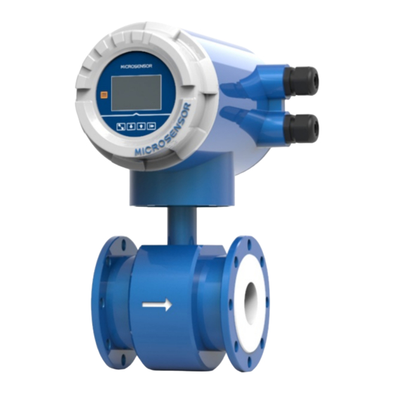
1 Introduction MFE600E Electromagnetic Flowmeter (hereinafter called Electromagnetic Flowmeter) is designed and manufactured with the most advanced domestic and abroad technology, featuring high accuracy, reliability, good stability and long service life. -
Page 4: Product Category
directly proportional to the velocity of conductive liquid, magnetic flux density and width of conductor (interior diameter of flowmeter). Such induced electromotive force is detected by a pair of electrodes on the tube wall of the flowmeter, and the equation of induced electromotive force is as follows: U = K×B×V×D U: Induced electromotive force K: Instrument Constant... -
Page 5: Outline Structure
5 Outline Structure IIntegrated flange connection dimensions Figure 2 Integrated Outline Dimension A: duct length of flowmeter; H: flowmeter height; N: bolt holes quantity; L: bolt hole diameter; K: center circle diameter of bolt hole; D: flange outside diameter. Integrated flowmeter dimensions Table 2 Integrated flowmeter dimensions Rated Pressure Outline Dimension(mm) - Page 6 Separated flange connection dimensions Figure 3 Separated Outline Dimension A: duct length of flowmeter; H: flowmeter height; N: bolt holes quantity; L: bolt hole diameter; K: center circle diameter of bolt hole; D: flange outside diameter. Separated flowmeter dimensions Table 3 Separated flowmeter dimensions Rated Pressure Outline Dimension(mm) Flange Connection Dimension(mm)
-
Page 7: Specifications
Separated converter dimensions 3× 7 The separated type is generally used in on-site maintenance and debugging reading inconvenient occasions, but also used in more severe applications, such as high-temperature fluids and vibration sources. On most occasions, the integrated and separated types can both meet the requirements. -
Page 8: Electrical Connection
4mA~20mA DC (load resistance 0Ω~750Ω, active output) Hart Frequency, pulse output (Passive, active output optional) Output signal Upper and lower limit alarm output RS485(Modbus protocol), RS232 Profibus-DP, Profibus-PA 2G,4G, NB, LoRa wireless transmission Electrical connection M20×1.5 IP65, IP68: submersible, long-term working in water, suitable for instrument installation in IP protection instrument well. -
Page 9: Separated Wiring
Table 5 Terminal Symbol Function T-/B RS485/RS232 communication output RS232 GND RS232 grounding wire T+/A RS485/RS232 communication input IOUT 4mA~20mA DC output; +24V DC COM 4mA~20mA DC output grounding wire; POUT Pulse/frequency output Pulse/frequency output grounding wire Alarm output for Upper Limit of flow Alarm output for Lower Limit of flow Pressure transmitter +IN +3.3V... -
Page 10: Installation
When wiring, select the corresponding power terminal to connect to the power line according to the product specifications, and then connect to the signal line according to the required output form. See Table 3 for the specific meaning of the integrated electromagnetic flowmeter wiring terminals. Table 6 Terminal definition of separated type Terminal Symbol Function... - Page 11 Figure6 Front and rear straight pipe installation In order to ensure the upstream piping conditions required for high accuracy measurement of the flowmeter, the piping installation as shown in the figure below is recommended. When there are valves at the front and rear of the flowmeter, the front and rear straight pipe must meet the front 5D and rear 2D installation methods at least, and the valve must be fully open, as shown in Figure 7.
- Page 12 Figure 10. Figure 10 When the flowmeter is installed at the back end of the valve and the valve is not fully open, the flowmeter and the back end of the valve need to ensure a straight pipe section of at least 10D, as shown in Figure Figure 11 Installation Direction When installing, the positive direction of liquid flow should generally be the same with the direction of the...
-
Page 13: Start Up Start Up
Figure 13 Flowmeter installation symmetrically with the pipe axis Sensor Grounding Since the voltage of inductive signal of electromagnetic flowmeter is small, it is easily affected by noise. Its reference potential must be the same to the measured liquid potential. Therefore, the reference potential of the sensor (terminal potential), the reference potential of converters and amplifiers are also the same to measured liquid potential, and the liquid potential have to be the same as the ground potential. -
Page 14: Converter Start-Up
9.2 Converter start-up The measuring instrument is composed of a sensor and a converter and is ready for immediate use when it is supplied. All operating data is factory set according to your order, please refer to the provided inspection report for details. After turning on the power, the flowmeter performs a self-check first. -
Page 15: Key Operation
Figure 15 Operation interface The meaning of the keys and operation methods are shown in Table 6. The composite key needs to press two keys at the same time. If there is no key operation within 10 minutes, it will automatically return to the main screen. -
Page 16: Parameters Setting
Day Report Month Report Year Report Power Report Figure 16 Report query interface Users can query 4 types of reports: daily, monthly, annual, and power outage reports. The meter can save up to 90 daily reports, 36 monthly reports, 3 annual reports and 20 power outage reports. Parameters setting 11.2 In the main interface state (Figure 8), press... - Page 17 m³/h,L/s,L/m,L/h,Ukg/s,Ukg/m,Ukg/h,Usg/s,U Flow Range Max Range setting sg/m,Usg/h,T/s,T/m,T/h,kg/s,kg/m,kg/h,m³/s, 282.7439 m³/h m³/m Damp Time Set 0.5S,0.8S,1.0S,2S,3S,4S,5S,6S,8S,10S,20S Damping time ,30S,50S,100S Zero Correct Set Zero velocity V= +0.000m/s correction Zero: +0.000m/s Low Flow Cutoff Data type: integer Small signal excision Range:0~100% 0.50 % Low Cutoff Mode Remove display Yes, NO Disable...
-
Page 18: Level 2 Menu
1m³,0.1m³,0.01m³,0.001m³,1L,0.1L,0.01L,0.0 Unit Totalizer Flow integration 01L,1t,0.1t,0.01t,0.001t,1kg,0.1kg,0.01kg,0.0 unit 01kg,1gal,0.1gal,0.01gal,0.001gal,1ig,0.1ig,0 0.001 m³ .01ig,0.001ig, Pulse Output Mode Pulse output Frequency output, pulse output method Frequency Frequency Range Frequency 1~5000 output range 1000 HZ LCD Brightness LCD screen 1~5 adjustable brightness 11.4 Level 2 menu Users enter the menu through level 2 password "29818”... - Page 19 Lower Threshold Lower limit Full scale percentage setting alarm value 20.00 % Current zero Current Zero Adj. point adjustable correction 0.9917 Current Current Full Adj. full-scale adjustable 0.9960 correction Excite Mode Excitation 4 types: 50 Hz,25 Hz,12.5 Hz,6.25 Hz method Mode 4 Excite Test Excitation...
- Page 20 Slope Limit Time Insensitive 0~99S adjustable time 10 s Buffer Size Acquisition 0~199 adjustable buffer depth Pressure Press Range Max sensor full 0.6MPa,1.0MPa,1.6MPa 0.6000 MPa scale Sensor Sensor Factor coefficient Factory set, unchangeable 1.0000 value Additional Factor Additional Factory set, unchangeable coefficient 1.0000 Converter Factor...
-
Page 21: Modbus Rtu Communication
Level 1 Password Level 1 password adjustable 00000 modification Level 2 Password Level 2 password adjustable 00000 modification Year-Month-Day Date-YY/MM/ adjustable 2 1 / 0 3 / 0 8 Hour-Min.-Sec. Time-HH/MM/ adjustable 1 1 / 5 7 / 4 9 System Run Time System 1 Day 13 Hour... - Page 22 message. The message body consists of hexadecimal numbers. Data definition: The cumulative amount is a 16-byte hexadecimal fixed point number, and the instantaneous amount (including flow, velocity, etc.) is a 4-byte IEEE 754 single-precision floating point number. Communication command: Function code 03(or 04)- reading display data Table 12 Send Receive...
- Page 23 Empty pipe alarm SHORT Upper limit alarm SHORT Lower limit alarm SHORT Flow rate information FLOAT Flow percentage FLOAT Electrode resistance FLOAT Instrument diameter FLOAT Positive total integer high LONG Reverse total integer high LONG Two-way total cumulative algebra and LONG LONG integers Two-way total cumulative algebra and...
- Page 24 Positive total decimal place message definition (FLOAT) Host sends: 01 03 00 05 00 02 D4 0A Slave response: 01 03 04 D0 D1 D2 D3 CRCL CRCH Positive total unit message definition(SHORT/ List type,same as reverse unit message) Host sends: 01 03 00 07 00 01 35 CB Slave response: 01 03 04 D0 CRCL CRCH D0 Definition: unit...
-
Page 25: Flow Range
Flow percentage message definition (FLOAT) Host sends: 01 03 00 14 00 02 84 0F Slave response: 01 03 04 D0 D1 D2 D3 CRCL CRCH The data are percentages, such as 100 for 100% and 1 for 1% Electrode resistance message definition (FLOAT) Host sends: 01 03 00 16 00 02 25 CF Slave response: 01 03 04 D0 D1 D2 D3 CRCL CRCH Electrode resistance unit defult as kΩ... -
Page 26: Responsibility
Velocity m/s Flow m³/h DN mm 0.0509 0.1018 0.2036 0.3054 0.4072 0.5089 0.7125 1.0179 0.1414 0.2827 0.5655 0.8482 1.1310 1.4137 1.9792 2.8274 0.3181 0.6362 1.2723 1.9085 2.5447 3.1809 4.4532 6.3617 0.5655 1.1310 2.2619 3.3929 4.5239 5.6549 7.9168 11.3097 0.8836 1.7671 3.5343 5.3014 7.0686... - Page 27 www.microsensorcorp.com...
Need help?
Do you have a question about the MFE600E and is the answer not in the manual?
Questions and answers