Table of Contents
Advertisement
Quick Links
Advertisement
Table of Contents

Related Manuals for Microsensor MFE600C


Summary of Contents for Microsensor MFE600C
- Page 1 MFE600C Operation Manual V1.0...
-
Page 2: Table Of Contents
Contents Introduction............................1 Specifications ............................1 Electrical Connection .......................... 2 Integrated wiring .......................... 2 Separated wiring .......................... 3 Start up ..............................4 Operation ............................. 6 Key instruction ..........................6 Key operation ..........................7 Parameter setting and method......................7 Report query ..........................7 Parameters setting ........................ -
Page 3: Introduction
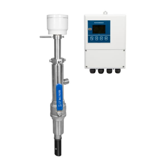
1 Introduction MFE600C Insert electromagnetic flowmeter (hereinafter referred to as plug-in flowmeter is designed and manufactured with the most advanced domestic and abroad technology. It has the characteristics of high reliability, good stability, and long service life. -
Page 4: Electrical Connection
IP65, IP68: submersible, long-term working in water, suitable for instrument installation in IP protection instrument well. Environmental temp. Working temp.: -20℃~60℃ Storage temp. -40℃~60℃ Relative humidity 5%~90% 3 Electrical Connection The Insert electromagnetic flowmeter converter can be divided into integrated converter and separated converter, and the wiring diagram is shown in Figure 1 and Figure 2. -
Page 5: Separated Wiring
+24V DC COM 4mA~20mA DC output grounding wire; POUT Pulse/frequency output Pulse/frequency output grounding wire Alarm output for Upper Limit of flow Alarm output for Lower Limit of flow Pressure transmitter +IN Pressure transmitter output terminal Pressure transmitter GND Electrode wire Signal grounding wire Electrode wire Power grounding wire... -
Page 6: Start Up
Terminal Symbol Function T-/A RS485/RS232 communication output RS232 GND RS232 grounding wire T+/B RS485/RS232 communication input I.mA 4mA~20mA DC output; Icom +24V Current output grounding wire 2-way flow pulse output/frequency output Pcom Pulse output grounding wire ALMH Alarm output for Upper Limit of flow ALML Alarm output for Lower Limit of flow Pressure transmitter +IN... - Page 7 Please check whether the running data of the power supply is correct. 4.2 Converter start-up The measuring instrument is composed of a sensor and a converter and is ready for immediate use when it is supplied. All operating data is factory set according to your order, please refer to the provided inspection report for details.
-
Page 8: Operation
The fluid is not filled with pipe; the media conductivity is less than 5us; the electrode is Electrode misconnected Upper flow limit The real-time flow value is higher than the set upper limit of alarm value Lower flow limit The real-time flow value is lower than the set lower limit of alarm value Operation Key instruction The electromagnetic flowmeter display and operation interface are shown in Figure 4. -
Page 9: Key Operation
Function Enter key for report, data reset and other functions Key operation The meter can enter the menu setting interface by simultaneously pressing the "shift" and "enter". Customers can choose the corresponding password to enter the menu for operation according to different needs. -
Page 10: Level 1 Password Menu
Level 1 password menu Users enter the menu through level 1 password "19818” and can set the parameters in the menu. The specific parameter information and data type are shown in Table 6. Table 6 Items Functions Setting/Instructions Parameter Range COM Address Communication Range:0~255... -
Page 11: Level 2 Menu
Flow Direction Flow direction Positive, reverse Forward Reverse Measure Reverse Yes, No measurement Enable Detect Empty Pipe Empty pipe Yes, No alarm Enable Empty pipe Empty Threshold As customers’ request alarm threshold 100.0 KΩ value 1m³ ,0.1m³ ,0.01m³ ,0.001m³ ,1L,0.1L,0.01L,0.0 Unit Totalizer Flow integration 01L,1t,0.1t,0.01t,0.001t,1kg,0.1kg,0.01kg,0.0... - Page 12 specific parameter information and data type are shown in Table 7. Table 7 Items Functions Setting/Instructions Parameter Range Upper Limit Alarm Upper limit Yes, No alarm Disable Upper Threshold Upper limit Full scale percentage setting alarm value 80.00 % Lower Limit Alarm Lower limit Yes, No alarm...
- Page 13 Current Mode Current output 0mA~10mA,4mA~20mA 4-20mA Output Test 20mA/2000Hz,10mA/1000Hz,4.16mA/ Output test 20Hz,4mA/1Hz Disable Density of Liquid Density As customers’ request measured 1.000 t/m³ fluid Slope Limit Change rate 0~100% adjustable limit value 30.0 % Slope Limit Time Insensitive 0~99S adjustable time 10 s Buffer Size...
- Page 14 Converter Factor Converter Factory set, unchangeable coefficient 1.0136 Converter SN. Converter Factory set, unchangeable code value 000018120162 Set Totalizer F. Positive total 000000000000007 adjustable preset 698305.887683732 L Set Totalizer R. Reverse total 000000000000007 adjustable preset 698305.887683732 L Level 1 Password Level 1 password adjustable 00000...
-
Page 15: Installation
System Time 2021/03/08 System time adjustable 11:57:54 LCD Brightness LCD screen 1~5 adjustable brightness 7 Installation The electromagnetic flowmeter must work under the condition of full pipe, and the flowmeter cannot work normally when the pipe is not full or empty. During installation, the positive direction of liquid flow should be consistent with the direction of the flow arrow on the sensor, and there must be enough space for installation and maintenance near the flowmeter. - Page 16 Figure 2 Straight pipes before and after installation In order to ensure the upstream piping conditions required for high accuracy measurement of the flowmeter, the piping installation as shown in the figure below is recommended. According to the position where the electromagnetic flowmeter is installed, when there are valves at the front and rear, the smallest straight pipe section must meet the installation distance of the first 10D and the rear 5D, and the valve needs to be fully opened, as shown in Figure 3.
-
Page 17: Modbus Rtu Communication
Figure 5 When the electromagnetic flow is installed at the rear end of the valve and the valve is not fully open, the plug-in electromagnetic flowmeter and the rear end of the valve must be at least the first 20D straight pipe section, as shown in Figure 6. - Page 18 Function code Function code Register address high Byte numbers Register address low (display address) Data 1 Register numbers high Data 2 Register numbers low Data 3 CRCH CRC Check code is high Data 4 CRCL CRC Check code is low CRCH CRC Check code is high CRCL...
- Page 19 Flow rate information FLOAT Flow percentage FLOAT Electrode resistance FLOAT Instrument diameter FLOAT Positive total integer high LONG Reverse total integer high LONG Two-way total cumulative algebra and LONG LONG integers Two-way total cumulative algebra and FLOAT decimal numbers Two-way cumulative algebra and symbols For a multi-byte number transmission, use the BIG-ENDIAN format, that is, use the format with high-weight bytes first and low-weight bytes after transmission.
- Page 20 Host sends: 01 03 00 03 00 02 34 0B Slave response: 01 03 04 D0 D1 D2 D3 CRCL CRCH definition (FLOAT) Positive total decimal place message Host sends: 01 03 00 05 00 02 D4 0A Slave response: 01 03 04 D0 D1 D2 D3 CRCL CRCH Positive total unit message definition(SHORT/ List type,same as reverse unit message)...
- Page 21 Host sends: 01 03 00 11 00 01 D4 0F Slave response: 01 03 02 00 T/F CRCL CRCH Flow rate message definition (FLOAT) Host sends: 01 03 00 12 00 02 64 0E Slave response: 01 03 04 D0 D1 D2 D3 CRCL CRCH unit defult as m/s definition (FLOAT)...
-
Page 22: Responsibility
0x00,0x00,0x06,0x40---------(LONG)number represent 1600 0x06,0x40-------------------(SHORT)number represent 1600 eg:(FLOAT)(number:-0.25) Host sends: 01 03 00 02 00 02 65 CB Slave response: 01 03 04 BE 80 00 00 DF F3 0xBE,0x80,0x00,0x00---------(FLOAT)number represent(-0.25) 9 Responsibility Within one year from the delivery date, we shall repair or replace the instrument with any quality fault caused by material parts or our manufacturing technique free of charge. - Page 23 www.microsensorcorp.com...
Need help?
Do you have a question about the MFE600C and is the answer not in the manual?
Questions and answers