Table of Contents
Advertisement
Quick Links
Advertisement
Table of Contents

Related Manuals for Microsensor MDM7000


Summary of Contents for Microsensor MDM7000
- Page 1 MDM7000 Operation Manual V1.1...
-
Page 2: Table Of Contents
Contents 1 Introduction .................... 1 2 Precautions for use ................2 3 Specifications ..................4 4 Outline construction and installation ............. 5 5 Electrical connection ................10 6 Menu operation ..................14 7 HART function ..................18 8 Operation, maintenance and fault diagnosis ........19 9 Unpacking, components and storage .......... -
Page 3: Introduction
Thanks for your using products from MICROSENSOR. To make the most of this product, it is recommended that you carefully read this manual before using it. 1 Introduction 1.1 Introduction MDM7000 series smart differential pressure transmitters adopt cutting-edge sensor technology for superior performance. They are used to measure the level, density, pressure and flow of liquid, gas or steam, convert the pressure signal into 4mA ~... -
Page 4: Precautions For Use
Incorrect installation, incorrect operation, or incorrect repairs by unauthorized body. The on-site pressure exceeds the maximum operating pressure of the instrument. Damages caused irresistible incidents, such earthquake, fire, war, etc. 2 Precautions for use a) The pressure transmitter should be installed, debugged, and maintained by professional engineers or technical personnel. - Page 5 Caution Indicates general faults that may result in minor personal injury or some property damage. Prompt Important information about the product, or a certain part of the manual needs prompting. Disclaimer We have conducted checks to ensure the consistency between the content in the printed materials and the hardware and software.
-
Page 6: Specifications
3 Specifications 3.1 Transmitter nameplate: Figure 1 Nameplate *Note 1: The nameplate certification is primarily based on the selection results, and the nameplate specifications are for illustrative purposes only. *Note 2: When it is a differential pressure transmitter, the maximum operating pressure becomes the maximum static pressure: 420bar. -
Page 7: Outline Construction And Installation
3.2 Main specifications: Power supply Rated voltage Output signal 4mA~20mA+HART Accuracy class 0.05%/0.075%/0.1% Long-term stability ±0.1% Span/5 Years ATEX Explosion-proof mark II 1G Ex ia IIC T4 Ga (Intrinsically safe) IECEX Explosion-proof mark Ex ia IIC T4 Ga (Intrinsically safe) ATEX explosion-proof mark... - Page 8 Explosion-proof type Ambient temperature with LCD -20℃~+70℃ display Ambient temperature with LCD -20℃~+70℃ display for Explosion-proof type Storage temperature with LCD -40℃~+85℃ display *The ambient temperature for explosion-proof/intrinsically safe transmitters should adhere to the group specified in the local area certification certificate.
- Page 9 b) Avoid installing the transmitter in corrosive conditions. If unavoidable, ventilation measures must be taken, and precautions should be in place to prevent rainwater from penetrating the cable. c) Although the transmitter is designed with shock and vibration resistance, caution should still be taken to avoid mechanical disturbances that could cause damage to the pressure transmitter.
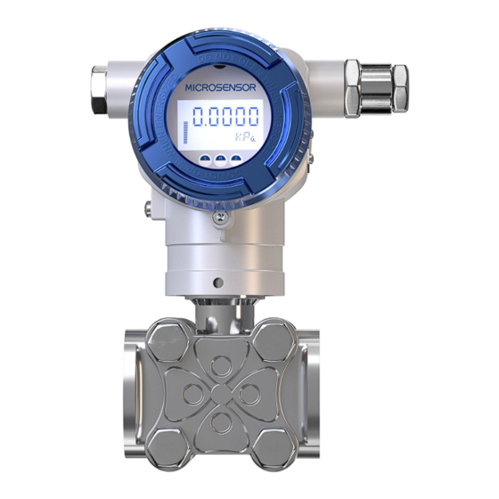
- Page 10 MDM7000 Transmitter With Display MDM7000 Transmitter Without Display Fixed screw Fixed screw Figure 3 Figure 2 MDM7000 Transmitter With D1 Adapter MDM7000 Transmitter With D2 Adapter Port: butt welding Por t : but t wel d i n g Figure 4 Figure 5...
- Page 11 AP/GP MDM7000 Transmitter With Display MDM7000 Transmitter Without Display Fixed screw Fixed screw Figure 6 Figure 7 Process Connection (M) Process Connection (G) Figure 8 Figure 9 Process Connection (A) Process Connection (N)
-
Page 12: Electrical Connection
Figure 10 Figure 11 5 Electrical connection 5.1 Electrical connection TEST LOOP Figure 12 During electrical installation, relevant guidelines must be followed. As the transmitter does not come with a power switch, overcurrent protection or power cut-off devices must be configured. Verify that the operating voltage aligns with the specifications indicated on the nameplate. - Page 13 Explosion-proof type and mark Explosion-proof type: Intrinsically safe, Flameproof Explosion-proof mark: II 1G Ex ia IIC T4 Ga/ Ex ia IIC T4 Ga II 2G Ex db IIC T6/T4 Gb/Ex db IIC T6/T4 G IP Rating: IP67 Intrinsically safe specifications: Ui: 30V, Ii: 100mA, Pi: 0.7W, Ci: 0μF;...
- Page 14 floating, and the control cabinet side being grounded c) Devices equipped with surge protectors must be grounded to ensure proper function. The most effective way to ground the transmitter housing is to directly connect the protective ground terminal to an impedance ≤5Ω to the ground. d) Try to avoid direct proximity to user devices or wiring of electrical and electronic devices that may cause interference.
- Page 15 250Ω Series resistor Power suppl y Figure 14 The communication mode of the transmitter is HART, and a brief description of the communication connection of the HART transmitter is as follows. The output of HART transmitter modulates HART digital signal besides the 4mA~20mA signal.
-
Page 16: Menu Operation
For current signal output with HART: 16.5V~55V DC. For Intrinsically safe current signal output: 18.5V~28V DC. 6 Menu operation 6.1 Button definition For the local buttons "S," "Z," and "M," there are three forms of button definitions as follows: 6.1.1 “Enter/Confirm”... - Page 17 after specification changes (such as immediately powering off and restarting without returning to the normal display mode after completing the operation settings), the changed specifications may not be confirmed. 6.2 LCD display window The transmitter has an LCD screen for variable display and setting operations.
-
Page 20: Hart Function
7 HART function The HART communication function of the transmitter is realized through HART related equipment, such as HART handheld terminal, supervisory control and data acquisition (SCADA) system with upper-level software, etc. 7.1 HART basic functions The basic functions of HART are the same as the “Menu operation” function in Chapter 6. -
Page 21: Operation, Maintenance And Fault Diagnosis
19) Factory resetting 20) Display device information Prompt For the specific operation of the HART function in the transmitter, please refer to the manuals of the HART-related equipment (such as handheld terminals and supervisory control and data acquisition (SCADA) system with upper-level software, etc.) 8 Operation, maintenance and fault diagnosis 8.1 Preparation and inspection before operation... - Page 22 conditions), it may be necessary to adjust the zero point of the transmitter to ensure measurement accuracy. Zero adjustment can be performed on-site using the transmitter's buttons following the instructions in section 7.4 of this manual, or it can be done using a handheld terminal or the supervisory control and data acquisition (SCADA) system with upper-level software.
- Page 23 care not to touch the isolated diaphragm (the end faces of the two process flanges must be kept in the same plane and maintained at the correct angle to the housing); Use a torque wrench to tighten the bolts and nuts diagonally and ...
- Page 24 resistance should be verified to ensure they meet the normal operating requirements. Furthermore, the correct setting and calibration of the measurement range should be assessed. Additionally, it is essential to check pressure leaks, blockages in the vent tube, unopened cut-off valves, and whether the installation site of the pressure transmitter is subjected to rapid temperature fluctuations.
- Page 25 transmitter should be drawn from the safety barrier. The safety barrier used should obtain relevant flameproof certification. The supply voltage is determined by the safety barrier specifications. (4) Load characteristics RL≤(VS-VM)V/0.021A Where RL——maximum load resistance, VS——power supply, VM=12V. 4mA ~ 20mA DC two-wire load (including signal receiving resistance and transmission wire resistance), 0Ω~1500Ω.
-
Page 26: Unpacking, Components And Storage
Medium temperature: -40℃~105℃(silicone oil) -40℃~85℃ (inert oil) Storage temperature:-40℃~+100℃ -40℃~+85℃ (with LCD display) (7) Applicable humidity Relative humidity: ≤95% (8) Overpressure and static pressure limit Differential pressure transmitter overpressure: 160bar Static pressure: 320bar(20℃±5℃), 420bar (-40℃~85℃) (9) Fault alarm When a fault occurs in transmitter component, the self-diagnosis program drives the output of a warning message or a settable alarm current according to the user's selection. -
Page 27: Responsibility
When opening the box, avoid forceful knocking to prevent damage to the instrument or accessories. 9.2 Components The pressure transmitter shipped from the factory shall include: MDM7000 Smart Pressure Transmitter 1 unit Operation Manual 1 copy Certificate of Conformity... -
Page 28: Naming
11 Naming MDM7000-DP Smart Differential Pressure Transmitter Items Code Description — MDM7000-DP Smart Differential Pressure Transmitter — Application of hazardous area China, Explosion-proof certification, No.CE23.6650 Ex db IIC T6~T4 Gb, GB/T3836.1-2021, GB/T3836.2-2021 China, Intrinsically safe certification, No.CE23.7688X Ex ia IIC T4 Ga, GB/T3836.1-2021, GB/T3836.4-2021... - Page 29 Wetted parts material Flange Discharge Diaphragm Sealings block valve/plug 316L 316L Glass-filled PTFE HC-276 HC-276 Glass-filled PTFE Process connection Drain/vent valve Specifications Thread Mounting method position Female 1/4-18NPT Rear end of flange 7/16-20UNF(F) Horizontal Above the side of Female 1/4-18NPT 7/16-20UNF(F) Horizontal flange...
- Page 30 Provide customer requested content according to project delivery standards E x t e n d e d w a r r a n t y 3-year warranty period 5-year warranty Note: Note: The specifications required for these options should be specified in the contract. MDM7000-DP-0HS1L-1A1S6H/G1-[CAL: 0-60mbar] Example: Example:...
- Page 31 MDM7000-GP/AP Smart Pressure Transmitter Items Code Description — MDM7000-GP Smart Gauge Pressure Transmitter — MDM7000-AP Smart Absolute Pressure Transmitter — Application of hazardous area China, Explosion-proof certification, No.CE23.6650 Ex db IIC T6~T4 Gb, GB/T3836.1-2021, GB/T3836.2-2021 China, Intrinsically safe certification, No.CE23.7688X Ex ia IIC T4 Ga, GB/T3836.1-2021, GB/T3836.4-2021...
- Page 32 Sensor structure Direct mounting Wetted parts material Diaphragm Process connection thread 316L 316L HC-276 316L Note Note: The material for the case connection is 304 Process connection M20×1.5 Male, φ3 vent hole, GB/T 193-2003 G1/2 Male, φ3 vent hole, GB/T 7307-2001 1/2-14NPT Male, φ6 vent hole, GB/T 12716-2011 1/2-14NPT Female, φ6 vent hole, GB/T 12716-2011 Fill oil...
- Page 33 Provide customer requested content according to project delivery standards E x t e n d e d w a r r a n t y 3-year warranty period 5-year warranty Note: Note: The specifications required for these options should be specified in the contract. MDM7000-GP-0HS1L-2TAMS/G1-[CAL: 0-0.4bar] Example: Example:...
Need help?
Do you have a question about the MDM7000 and is the answer not in the manual?
Questions and answers