Table of Contents
Advertisement
Quick Links
Advertisement
Table of Contents

Related Manuals for Microsensor MDM7000


Summary of Contents for Microsensor MDM7000
- Page 1 MDM7000 Operation Manual V3.0...
-
Page 2: Table Of Contents
Contents 1 Introduction .................... 1 2 Precautions for use ................2 3 Specifications ..................4 4 Outline construction and installation ............. 6 5 Electrical connection ................26 6 Intrinsically safe use ................31 7 Menu operation ..................34 8 HART function ..................37 9 Operation, maintenance and fault diagnosis ........ -
Page 3: Introduction
Thanks for your using products from MICROSENSOR. To make the most of this product, it is recommended that you carefully read this manual before using it. 1 Introduction 1.1 Introduction MDM7000 series smart differential pressure transmitters adopt cutting-edge sensor technology for superior performance. They are used to measure the level, density, pressure and flow of liquid, gas or steam, convert the pressure signal into 4mA ~... -
Page 4: Precautions For Use
period that is not due to user error, repairs will be free of charge in principle. b) After a fault occurs, the user can contact the distributor or Micro Sensor. Please provide relevant information such as instrument model and specifications, product nameplate information (including ID), order information, fault description, and environmental conditions so that the failure can be resolved... - Page 5 being mindful of the potential presence of high voltage in the circuit. c) When using the pressure transmitter in hazardous environments, installation, operation, and maintenance should adhere to the relevant regulations in this manual and national standards. d) Disassembly of the instrument is only permitted under atmospheric pressure.
-
Page 6: Specifications
The data in the printed materials has been verified according to regulations, and necessary calibration will be included in the next version. 3 Specifications 3.1 Transmitter nameplate: Figure 1 Nameplate Note 1: The nameplate certification is primarily based on the selection results, and the nameplate specifications are for illustrative purposes only. - Page 7 3.2 Main specifications: 60mbar~30bar 0.4bar~400bar 0.4bar~100bar 60mbar~400bar Range ① 0.4bar~100bar GP-T 0.4bar~100bar AP-T 0.4bar~10bar 0.4bar~2.5bar 0.4bar~2.5bar 0.05 0.075 0.075 Accuracy class GP-T AP-T Intrinsically safe 18.5V~28V DC HART Power supply Non intrinsically 16.5V~55V DC safe HART ② Output signal 4mA~20mA,HART Long-term stability(Non ±0.1%SPAN/5 years diaphragm seal system)...
-
Page 8: Outline Construction And Installation
IECEX Explosion-proof mark Ex ia IIC T4 Ga (Intrinsically safe) ATEX Explosion-proof mark II 2G Ex db IIC T6 Gb (Flameproof) IECEX explosion-proof mark Ex db IIC T6 Gb (Flameproof) Note①:For detailed measuring range, see Chapter 12 Product spectrum; Note②:Non intrinsically safe power supply voltage can be selected as 10.5V. 4 Outline construction and installation 4.1 Installation conditions 4.1.1 Natural conditions... - Page 9 equipment [ ℃ ] [ ℃ ] 200≥T>135 135≥T>100 100≥T>85 4.1.2 Electromagnetic conditions Radiated interference: ≤1000MHz Radio-frequency interference: ≤10V/m (80MHz~1GHz) Electrostatic interference: ≤8kV Power frequency interference: ≤30A/m 4.1.3 Mechanical conditions Vibration acceleration: ≤3g 4.1.4 Installation position a) Please endeavor to minimize variations in temperature or the existence of apparent thermal gradients.
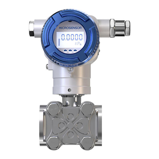
- Page 10 Caution It is recommended to avoid installing in areas with large temperature differentials, prone to condensation, susceptible to icing, and high levels of vibration. 4.2 Outline construction *Based on the specific order, the equipment comprises various components. Figure 2 Transmitter outline construction a) The electronic device housing is constructed from die-cast...
- Page 11 aluminum or precision-cast stainless steel. b) The housing features detachable circular protective covers on the front and rear sides, with fixed screws on the front side to prevent the protective cover from loosening or detaching. c) Based on the model, the front cover (1) can be designed as a viewing window, allowing direct reading of measured values from the LCD display (2).See Figure 29 for details.
- Page 12 Once the installation position is confirmed, tighten the screws again. This method minimizes the impact on electronic circuit connections and output displays. Installation as shown in the following: 4.3.1 Outline Construction and overall dimensions Unit: mm MDM7000-DP With Display Figure 3 With D1 Adapter With D2 Adapter...
- Page 13 Figure 6 Figure 7 MDM7000-GP&AP With Display(F) With Display(M) Figure 9 Figure 8...
- Page 14 Process connection(M) Process connection(G) Figure 11 Figure 10 Process connection(A) Process connection(N) Figure 13 Figure 12 MDM7000-GP-T&AP-T Remote Flange Insertion Sleeve With Remote Flange With Display Display...
- Page 15 Figure 14 Figure 15 Direct Mounted Single Flange With Direct Mounted Single Thread With Display Display Figure 17 Figure 16 MDM7000-LT Side Mounted Flange Insertion Sleeve Side Mounted Flange With Display With Display Figure 18 Figure 19...
- Page 16 Remote Flange Insertion Sleeve With Remote Flange With Display Display Figure 20 Figure 21 MDM7000-LP Side Mounted Movable Flange Insertion Side Mounted Movable Flange + Sleeve+ Remote Fixed Flange With Remote Fixed Flange With Display Display Figure 23 Figure 22...
- Page 17 + Remote Fixed Flange With Display With Display Figure 26 Figure 27 Note:MDM7000 Transmitter With Display is Same as Without Display. Warning During the transportation of the diaphragm flange, please pay attention to the protection of the flange diaphragm; for DGP/DAP, please pay attention to the...
- Page 18 4.3.2 Valve manifold option and description Various valve manifolds are available, as illustrated below: Figure 28 Two-valve manifold Figure 30 Five-valve manifold Figure 29 Three-valve manifold The two-valve manifold consists of a shut-off valve (on/off or conducting) and a drain valve (typically for waste, water, or gas). Its function is to open or close the pipeline, and during installation, the flow direction of the applicable medium shall align with the direction indicated by the arrow on the valve body.
- Page 19 valves, and a balancing valve. It can be classified based on each valve's function within the system as follows: positive cavity shut-off valve, negative cavity shut-off valve, with a balancing valve in between. Three-valve manifold is used in conjunction with a differential pressure transmitter to connect or disconnect the positive and negative pressure measurement cavity with process pipeline, or to connect or disconnect the positive pressure cavity with the negative pressure cavity.
- Page 20 For correct installation, it is recommended to follow: The vent tube shall be kept as short as possible and avoid sharp bends. The slope of the vent tube shall not be less than 1:12 to prevent sedimentation. Before connecting to the transmitter, the vent tube must be ...
- Page 21 Figure 31 Connection between transmitter and waist-shaped flange Figure 32 Connection between transmitter and T-shaped flange 4.3.4 Vent tube mounting (1) System pressure port The sediment and residual fluid inside the pressure pipeline entering the vent tube can cause measurement errors during pressure measurement.
- Page 22 When the process medium is liquid, the pressure port shall be installed horizontally or within 45° below the horizontal. When the process medium is gas, the pressure port should be installed vertically upwards or within 45°of the vertical upward. When the process medium is steam, the pressure port shall be installed horizontally or within 45°above the horizontal.
- Page 23 errors. When measuring steam, the liquid in the vent tube may condense and evaporate repeatedly due to changes in process temperature or environmental conditions. This can lead to the formation of liquid columns in the high and low-pressure sides, resulting in measurement errors due to varying liquid column heights.
- Page 24 Figure 34 DP horizontal piping installation (horizontal installation pipe)
- Page 25 Figure 35 GP horizontal piping installation (horizontal installation pipe ) 4.3.6 Vertical piping installation The vertical piping installation (pressure process connection) for the transmitter utilizes a pipe-mounted bending bracket + U-bolt + on-site installation pipe. The installation pipe diameter ranges from Φ50 to Φ60mm.
- Page 26 Figure 36 DP vertical piping installation(horizontal installation pipe)
- Page 27 Figure 37 GP vertical piping installation(horizontal installation pipe) Prompt After the installation of the transmitter, the positive and negative pressure ports shall be at the same level as possible.
-
Page 28: Electrical Connection
5 Electrical connection 5.1 Electrical connection Figure 38 During electrical installation, relevant guidelines must be followed. As the transmitter does not come with a power switch, overcurrent protection or power cut-off devices must be configured. Verify that the operating voltage aligns with the specifications indicated on the nameplate. - Page 29 5.1.1 2-wire electrical connection Figure 39 Electrical connection between transmitter and external power supply Precautions: a) Keep the circuit connections as short as possible; b) Select shielded twisted-pair signal cables for optimal grounding. To avoid ground loop, the shield layer should be single-ended grounded, with the pressure transmitter side being insulated and floating, and the control cabinet side being grounded c) Devices equipped with surge protectors must be grounded to...
- Page 30 g) Avoid nearby high-power electrical equipment and utilize shielded cables (the shielding layer is well grounded at both ends). Warning For flameproof transmitters, under powered conditions, it is strictly prohibited to open the rear cover or front glass. Therefore, during on-site use, hand terminal should not be used to calibrate the transmitter, but the transmitter buttons can be used for calibration.
- Page 31 terminals of the transmitter or across the two terminals of the load resistor. The transmitter can be used in conjunction with all HART-compatible instruments in the system, such as actuators and valve positioners. HART terminal devices can be used to individually operate and control these instruments.
- Page 32 Figure 41 b) Explosion-proof flexible tube protection system: In hazardous areas where flameproof pressure transmitters are installed and utilized, a metal explosion-proof flexible tube shall be employed to connect the signal cable to the junction box and extend it to the safe area. Figure 42 5.3 Power supply It is recommended to use a dedicated linear DC power supply to...
-
Page 33: Intrinsically Safe Use
and display devices to ensure that it meets the requirements for the terminal voltage. For current signal output with HART: 16.5V~55V DC. For Intrinsically safe current signal output: 18.5V~28V DC. 6 Intrinsically safe use The nameplate of the intrinsically safe transmitter indicates the explosion-proof category, class, and temperature group according to GB 3836.1-2000 "Explosive atmospheres - Part 1: Equipment - General requirements". - Page 34 Non-hazardous area Hazardous area Power Safety supply barrier 24VDC [Ex ia Ga] IIC Ex ia IIC T4 Ga Uo:Maximum output voltage of safety barrier Ui:Transmitter maximum input voltage Io: Maximum output current of safety barrier Ii: Transmitter maximum input current Po: Maximum output power of safety barrier Pi: Transmitter maximum input power Lo:Maximum external inductance of safety barrier...
- Page 35 Li -- Transmitter maximum internal inductance; Cc - Maximum allowable distributed capacitance of connecting cable; Lc - Maximum allowable distributed inductance of connecting cable When using intrinsically safe instruments in hazardous areas, maintenance work should be limited to zero and range adjustment, while other components shall be inspected and repaired in non-hazardous locations.
-
Page 36: Menu Operation
7 Menu operation 7.1 Button definition For the local buttons "S," "Z," and "M," there are three forms of button definitions as follows: 7.1.1 “Enter/Confirm” Press button "M," hold for 0.1s, then release; each execution of this operation inputs an "Enter/Confirm" function. 7.1.2 “Set/Switch”... - Page 37 7.3 Overall process for button operation Set Primary Set process Press M to Set URL Set LRV variable display Manu variable unit S e t P r i m a r y Set LRV Set damping Fixed current output time Set the v a r i a b l e d i s p l a y Set output...
-
Page 39: Hart Function
8 HART function The HART communication function of the transmitter is realized through HART related equipment, such as HART handheld terminal, supervisory control and data acquisition (SCADA) system with upper-level software, etc. 8.1 HART basic functions The basic functions of HART are the same as the “Menu operation” function in Chapter 6. -
Page 40: Operation, Maintenance And Fault Diagnosis
19) Factory resetting 20) Display device information Prompt For the specific operation of the HART function in the transmitter, please refer to the manuals of the HART-related equipment (such as handheld terminals and supervisory control and data acquisition (SCADA) system with upper-level software, etc.) 9 Operation, maintenance and fault diagnosis 9.1 Preparation and inspection before operation... - Page 41 nameplate, the output current signal should be within the range of 4mA to 20mA. If the pressure is below the calibrated measuring range, the output signal displays 3.8mA. Conversely, if the pressure is over the calibrated measuring range, the output signal displays 20.8mA.
- Page 42 Loosen the bolts of the process flange in a diagonal direction with care; Carefully remove the flange to avoid causing mechanical damage to the sensor isolated diaphragm; Clean the sensor diaphragm with a soft-bristled brush and an appropriate solvent, which can be done along with cleaning the flange;...
- Page 43 without a corresponding signal output or if the output is not proportional, it could be due to transmitter abnormalities. In this case, the polarity or circuit of the power supply, as well as voltage, power consumption, and load resistance, should be inspected to ensure they meet the normal operating requirements.
- Page 44 (3) Power Supply 4mA ~ 20mA DC two-wire system, linear or square root output available. When there is no load, the supply voltage is 10.5V DC. 4mA ~ 20mA DC, HART two-wire system, linear or square root output available. When the load is 250Ω, the supply voltage is 16.5V ~...
- Page 45 transmitter: -40℃~+70℃ The ambient temperature for intrinsically safe transmitter: -20 ℃~+70℃ (with LCD display) *The ambient temperature for intrinsically safe transmitters should adhere to the group specified in the local area certification certificate. Storage temperature:-40℃~+100℃ (Silicone oil) -40℃~+160℃ (Inert oil) 0℃~+315℃...
- Page 46 Intrinsically safe explosion-proof standards: GB/T 3836.1-2021, GB/T 3836.4-2021, intrinsically safe mark: Ex ia IIC T4 Ga; Flameproof and explosion-proof standards: GB/T 3836.1-2021, GB/T 3836.2-2021, flameproof mark: Ex db ⅡC T6 Gb; Dust explosion-proof standards: GB/T 3836.1-2021, GB/T 3836.31-2021, dust explosion-proof mark: dust explosion-proof mark: Ex tb IIIC T85℃...
- Page 47 Flameproof mark: Ex db IIC T6 Gb; Dust explosion-proof standards: IEC 60079-0, IEC 60079-31; Dust explosion-proof mark: Ex tb IIIC T80℃ Db; IP rating reference standard: IEC 60529. Housing: IP67. Canada’ s explosion-proof mark and performance Division system intrinsically safe standard: CSA C22.2 No. 60079-0:19, CAN/CSA C22.2 No.
- Page 48 Class II, Division 1 Group E, F and G T80ºC Class III Zone system flameproof standards: CAN/CSA-C22.2 No. 60079-0:19, CAN/CSA-C22.2 No. 60079-1:16, CAN/CSA-C22.2 No. 60079-31:15, ANSI/UL 60079-0-2020 Seventh Edition, ANSI/UL 60079-1-2020 Seventh Edition, ANSI/UL 60079-31-2015 Second Edition Zone system flameproof mark: Ex db IIC T6 Gb Class I, Zone 1, AEx db IIC T6 Gb Ex tb IIIC T80℃...
- Page 49 ±(0.001+0.0148TD)% 60mbar* TD> 0.4bar, 2.5bar, 10bar, ±(0.0025+0.0095TD)% 30bar ±0.1% 0.4bar, 2.5bar TD≤5 10bar, 30bar, 100bar, ±0.075% 400bar ±(0.025+0.015TD) % 0.4bar, 2.5bar TD> 10bar, 30bar, 100bar, ±(0.0025+0.0145TD) % 400bar ±0.2% 0.4bar, 2.5bar TD≤5 ±0.1% 10bar, 100bar ±(0.025+0.035TD) % 0.4bar, 2.5bar TD> ±(0.025+0.015TD) % 10bar, 100bar 60mbar*,100bar,...
- Page 50 5 < 2.5bar,10bar,30bar,100 TD < ±0.2%SPAN TD≤5 ±0.1%SPAN 5 < 0.4bar, 2.5bar,10bar TD < ±0.2%SPAN TD ≤ ±0.25% + Diaphragm 0.4bar, 2.5bar seal system effects ±(0.025%×0.045TD)% < TD>5 + Diaphragm seal 0.4bar, 2.5bar system effects (2) Long-term stability δ≤±0.1% SPAN/10 years δ≤±0.2% SPAN/5 years(only LT/LP)...
- Page 51 Model Ambient temperature effects At 60mbar, the total effect per 10℃ is (0.1+0.05TD)%SPAN;For other ranges:total effect per 10℃:(0.075+0.0375TD)%SPAN ±(0.075+0.0375TD)%10℃ of Span ±(0.085+0.0625TD)%10℃ of Span ±(0.075+0.0375TD) % 10℃ of SPAN ±(0.125+0.075TD) % 10℃ of SPAN at 60mbar ±(0.115+0.065TD) % 10℃ of SPAN at other ranges Note 1: The specification is only for base products.
- Page 52 (2) Process connection Drain/vent valve Specifications Thread position Female 1/4-18NPT Rear end of flange 7/16-20UNF(F) Above the side of Female 1/4-18NPT 7/16-20UNF(F) flange Under the side of Female 1/4-18NPT 7/16-20UNF(F) flange Female 1/4-18NPT Side drain/vent valve 7/16-20UNF(F) (3) Wetted parts Diaphragm ...
-
Page 53: Unpacking, Components And Storage
When opening the box, avoid forceful knocking to prevent damage to the instrument or accessories. 10.2 Components The pressure transmitter shipped from the factory shall include: MDM7000 Smart Pressure Transmitter 1 unit Operation Manual 1 copy Certificate of Conformity... -
Page 54: Warning
temperature should be maintained between -40℃~100℃. 11 Warning During installation, it is essential to ensure reliable grounding of the housing. The product's housing material contains aluminum. When used in 0 area, precautions must be taken to prevent ignition hazards caused by impact or friction. 12 Product spectrum...
Need help?
Do you have a question about the MDM7000 and is the answer not in the manual?
Questions and answers