Advertisement
Quick Links
Advertisement

Related Manuals for Microsensor MPM


Summary of Contents for Microsensor MPM
- Page 1 MPM/MDM4760 Operation Manual V2.1...
-
Page 2: Specifications
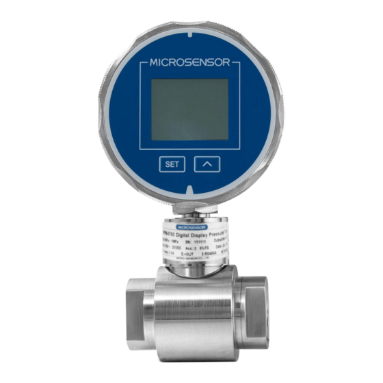
Thank you very much for selecting Micro Sensor’s product, please take some time to read this operation manual very carefully before using the product. 1 Introduction MPM/MDM4760 transmitter is a new-developed digital intelligent transmitter with high accuracy & good stability, and can provide prompt measurement displaying... - Page 3 MPM4760 pressure transmitter: Measure range:-100kPa…0kPa~10kPa…100MPa Overpressure:1.5 times FS or 110MPa(Min. value is valid) MDM4760 differential pressure transmitter: Measure range:0kPa~35kPa…3.5MPa +overpressure: 2 times FS -overpressure:FS Max.static pressure:≤20MPa ① Total Accuracy :±0.25%FS Stability: ±0.2%FS/YEAR Compensated Temp.: -10℃~70℃ Working Temp: -30℃~80℃ Storage Temp: -40℃~85℃ Power Supply: 8V~28V DC or Battery supply Output signal Standard: analog 4mA~20mA DC, 2-wire;...
- Page 4 Weight: ~420g Housing: stainless steel Diaphragm: stainless steel 316L O- Ring: Viton ①:Total accuracy including:Lin.+Hys.+ Rep.+ Zero Temp. Error + Sensitivity Error (be suitable for basic range) 3 Outline Construction and Installation 3.1 Outline construction(Unit: mm) MPM4760 pressure transmitter: φ φ...
- Page 5 MDM4760 differential pressure transmitter: φ φ G1/4 3.2 Installation 3.2.1 Notes for installation...
- Page 6 a) Measured pressure shall not be beyond the scope of transmitter pressure range; b) Media should be compatible with the contacting parts of transmitter; c) Be sure the pressure hole shall not be blocked by media. 3.2.2 Installation procedure for Pressure transmitter The transmitter usually is installed upward and perpendicular to the horizontal direction.
-
Page 7: Electric Connection
4 Electric Connection Output Signal Function Pins Cable Black 4~20mA DC,2-wire +OUT Communication RS485A Yellow RS485B White interface The electrical connection of transducer with 2-wire,4~20mADC output to see below. transmitter 28V DC P Input DC mA Meter 20mA DC Load Output I +OUT The electrical connection of transducer with 4mA~20mADC output and... - Page 8 “UP”; b) Please be sure do not knock at the package violently, and protect the housing jacket and rubber bushing. 5.2 Components MPM/MDM4760 pressure/differential pressure Transmitter Product instruction manual Certificate of quality Software due to the order 5.3 Storage...
-
Page 9: Assistant Software
Setonline Software downloaded website: www.microsensor.cn 7 Parameter Setup and Calibration 7.1 Display and Press Key Instruction The two keys on the front panel are “SET” and “∧” respectively.“ ∧ ”key is used for parameter modification. “SET” key is used for choosing... - Page 10 7.2 Basic Parameter Setup We have calibrated the transmitter according to your requirements when the products are out of factory, you could operate it directly. However, you also could modify or calibrate the parameter in the worksite due to 7.2 and 7.3. 7.2.1 Under measurement situation, press “SET”...
- Page 11 XXXXX Zero display value setup------ ∧ / ∧ +SET XXXXX FS display value setup------- ∧ / ∧ +SET XXXXX 4mA output pressure value---- ∧ / ∧ +SET XXXXX 20mA output pressure value --- ∧ / ∧ +SET XXXXX rezero /nrz operation------------ ∧...
- Page 12 1200/…9600 Baud rate setup option--------- ∧ bArd 01/…99 Transducer address option----- ∧ / ∧ +SET Addr ∧ / ∧ +SET XXXX 4mA output calibration--------- dA0F XXXX 20mA output calibration ------- ∧ / ∧ +SET dAFF yES/no Restore factory setting or not-- ∧...
- Page 13 7.2.2 Under parameter modification situation, press “∧”and“∧+SET” to modify the current parameter value, then press “SET” to make sure. The transmitter indicates the next parameter note sign automatically; 7.2.3 Repeat steps (1) and (2) to modify other parameters, then the transmitter returns to measurement situation automatically;...
- Page 14 a) Under measurement situation, short pressing “∧”key(no more than 2 seconds), the vice display indicates max. value, min. value, percentage, output current, temperature and pressure unit. b) Under measurement situation, long pressing“∧”key(more than 2 seconds) , the transmitter will clear the vice display’s record of max. value and min.
- Page 15 c) Please do not pull the cable violently or press the diaphragm with sharp or hard metal, etc. d) Please dispose the waste batteries properly to avoid polluting the environment. 8.3 Failure identification If the transmitter is failure, such as no output or output unstable, ect. Please shut the power first, then check if the installation and cable connection conform to manual, power voltage is correct or not, vented tube is unobstructed or not and the system works well or not.
Need help?
Do you have a question about the MPM and is the answer not in the manual?
Questions and answers