
Related Manuals for schmersal AZM400Z-ST-I1-1P2P-T


Summary of Contents for schmersal AZM400Z-ST-I1-1P2P-T
-
Page 1: Table Of Contents
操作与安装指示 Solenoid interlock AZM400Z-ST-I1-1P2P-T Table of Contents 1 About this document 1.1 Function 1.2 Target group of the operating instructions: authorised qualified personnel 1.3 Explanation of the symbols used 1.4 Appropriate use 1.5 General safety instructions 1.6 警告 1.7 免责条款... -
Page 2: Function
"Product description". 1.5 General safety instructions 用户必须遵守本说明书以及国家特定的安装标准,以及安全和事故预防规定中的安全指示。 Further technical information can be found in the Schmersal catalogues or in the online catalogue on the Internet: products.schmersal.com. 我司对所有信息不承担责任,且对技术变更权利予以保留。 There are no residual risks, provided that the safety instructions as well as the instructions regarding mounting, commissioning, operation and maintenance are observed. -
Page 3: 免责条款
1.6 警告 In case of inadequate or improper use or manipulations of the component, personal hazards or damage to machinery or plant components cannot be excluded. 1.7 免责条款 We shall accept no liability for damages and malfunctions resulting from defective mounting or failure to comply with the operating instructions manual. -
Page 4: Special Versions
无 不带电子手动解锁(仅用于ST) 带电子手动解锁(仅用于ST2) Actuator AZM400-B1 Versions AZM400Z-...-BOW may only be used in connection with Bowden cable release ACC-AZM400-BOW-.M-.M, which is available as accessory. Use without the Bowden cable release fitted is not permissible. Observe the additional notes in the operating instructions of the Bowden cable release. - Page 5 证书 TÜV cULus ANATEL 总体数据 标准 EN ISO 13849-1 EN ISO 14119 EN IEC 60947-5-3 EN IEC 61508 通用信息 独立编码 编码等级,依据EN ISO 14119 高 作用原理 磁场 RFID Frequency band RFID 125 kHz Transmitter output RFID, maximum -6 dB/m 外壳材料 轻合金压铸 100 ms 操动件关闭时的响应时间安全输出,最大值...
- Page 6 PFD值 9.00 x 10⁻⁵ 安全完整性等级 (SIL),适用于以下应用 任务时间 20 年 安全评估 - 防护锁定 性能水平,最高 控制类别 PFH值 1.80 x 10⁻⁹ /h PFD值 1.60 x 10⁻⁴ 安全完整性等级 (SIL),适用于以下应用 任务时间 20 年 机械参数 联锁原理 双稳定 机械寿命,最少 1,000,000 操作 注(机械寿命) 具有横向力的Ftransr= 100 N: 100.000 次操作 Allowed distance interlock to actuator, minimum 1 mm Allowed distance interlock to actuator, maximum...
- Page 7 防护等级 IP67 IP66 Ambient temperature -20 ... +55 °C 储存和运输温度,最小 -40 °C 储存和运输温度,最大 +85 °C 最大相对湿度 93 % 注(相对湿度) 无冷凝 不结冰 抗振性,依据EN 60068-2-6: 10 ... 150 Hz,振幅 0.35 mm 抗冲击 30 g / 11 ms 防护等级 允许安装海拔高度,最大值 2,000 m Ambient conditions - Insulation values 额定绝缘电压...
- Page 8 分类 ZVEI CB24I,信号源 Current consumption at 24V, minimum 5 mA Current consumption at 24V, maximum 10 mA 允许的差异时间(输入),最大 10 s Test pulse interval, maximum 40 ms Test pulse duration, maximum 5 ms Permissible residual drive current 1.5 mA Electrical data - Safety digital outputs 指定,安全输出...
-
Page 9: General Mounting Instructions
This device complies with the nerve stimulation limits (ISED CNR-102) when operated at a minimum distance of 100 mm. In the event of changes or modifications that have not been expressly approved by K.A. Schmersal GmbH & Co. KG, the user's authorisation to use the device may become ineffective. - Page 10 Please observe the remarks of the standards EN ISO 12100, EN ISO 14119 and EN ISO 14120. Any position is possible. The accumulation of fine-grained dirt in the bolt area must be avoided. In such a case it is therefore not advised to have vertical mounting, where the bolt goes upwards from below. For the correct fixing of the solenoid interlock, the device is provided with two mounting holes for M6-screws.
- Page 11 The approach direction must only be from the X and Y directions. The maximum distance of 7 mm between the actuator and the solenoid interlock must be maintained so that the stipulated holding force and the safe clamping function is achieved according to SIL 3. The construction of the guard door is to be designed so that it is not possible to move the guard system with the actuator on the Z axis so far that the distance between the interlock and the actuator is greater than 7 mm.
-
Page 12: Manual Release
3.2 Manual release For the machine set-up, the solenoid interlock can be unlocked in a de-energised condition. Turning the triangle of the manual release using the triangular key to the position releases the solenoid interlock. The normal locking function is only restored after the manual release has been returned to its original position Triangular key TK-M5 (101100887) available as accessory. -
Page 13: Emergency Exit -T
independently of the control inputs. Then no other actions are required, the safety and diagnostic units remain off. System condition (only valid during the initialising phase): Main supply Auxiliary supply System condition Locking bolt remains in position (safety outputs switched off) 24 V dependent on the control inputs 24 V... -
Page 14: Dimensions
3.6 Dimensions All measurements in mm. AZM400Z-ST AZM400Z-ST2 14-27... -
Page 15: Actuator And Accessories
AZM400 with emergency exit AZM400Z-ST..-T AZM400Z-ST2..-T Manual release with cover Emergency Exit Locking bolt (extended) Connector plug M12, 8-pole Connector plug M12, 5-pole RFID Sensor 3.7 Actuator and accessories Actuator AZM400-B1 (not included in delivery) 15-27... - Page 16 Mounting plate, part of the mounting set MS-AZM400 (available as accessory) Lockout tag SZ400 (available as accessory) For detailed information and assembly instructions, see operating instructions SZ400 16-27...
-
Page 17: 电气连接
Bowden cable release ACC-AZM400-BOW-.M-.M (available as accessory) Observe the additional notes in the operating instructions of the Bowden cable release. 4 电气连接 4.1 电气接线指示 电气接线需在电源关闭的情况下由授权专业人员完成。 17-27... -
Page 18: Control Options In The Normal Operating Mode
The voltage inputs A1 (and H1 with the AZM400Z-ST2..), and the control inputs E1, E2 and E3 must have a permanent protection against over-voltage. The use of PELV Supply units according to EN 60204-1 is recommended, The safety outputs can be integrated into the safety circuit of the control system. 所需的电缆保险丝保护必须集成在安装中。... -
Page 19: Requirements For The Connected Safety-Monitoring Module
100 ms. The safety inputs of the safety-monitoring module must be able to blank a test impulse of < 1 ms. Information for the selection of suitable safety-monitoring modules can be found in the Schmersal catalogues or in the online catalogue on the Internet: products.schmersal.com. - Page 20 Function safety Pin configuration of the Colour codes of the Possible colour code of switchgear connector M12. 8-pole Schmersal connector plugs other commercially to DIN 47100 available connector plugs according to EN 60947-5-2 Control input 1 Safety output 1...
-
Page 21: Wiring Examples
Function safety Pin configuration of the Colour codes of the Possible colour code of switchgear connector M12, 5-pole Schmersal connector plugs other commercially to DIN 47100 available connector plugs according to EN 60947-5-2 Functional earth connection 3... -
Page 22: Actuator Teaching / Actuator Detection
Key, wiring Connector plug M12, 8-pole Control input 1 Control input 1 Control input 2 Safety output 1 Safety output 2 Diagnostic output Wiring example 2: AZM400Z-ST2 Key, wiring Connector plug M12, 8-pole Connector plug M12, 5-pole Control input 1 Control input 2 Control input 3 Safety output 1... -
Page 23: 主动原理和诊断功能
采用标准编码的电磁安全锁到货即可使用。 单独编码的电磁安全锁以及操动件需要进行以下示教步骤: 1. 关闭电磁锁的电源并重新接通。 2. 将操动件置于探测范围内。电磁安全锁将显示示教正在进行中,红色LED亮起,黄色LED闪烁(1 Hz)。 3. 10秒过后,快速闪动黄色信号(3 Hz)提示断开电磁锁的有效电压。(如果电压在5分钟内未断开,电磁安全锁将中断示教步骤并闪烁5次红灯,表示操动件错误)。 4. 一旦工作电压重新接通,必须再次检测操动件,以激活已示教的操动件代码。这一操作将确定保存已激活的编码! 对于订购后缀为-I1的设备,安全开关设备和操动件的执行分配是不可逆的。 对于订货后缀为- I2的设备,可无限次地重新示教新的操动件。示教新操动件时,此前的编码将作废。随后,将启动一个为时10分钟的放行阻止程序,此间防止更 Make organisational measures against possible manipulation with other actuators in case that a standard coded variant is used. 6 主动原理和诊断功能 6.1 安全输出的工作方式 With the solenoid interlock AZM400, the unlock signals immediately switch off the safety outputs. The unlocked guard system can be locked again as long as the actuator is within the detection range of the solenoid interlock. -
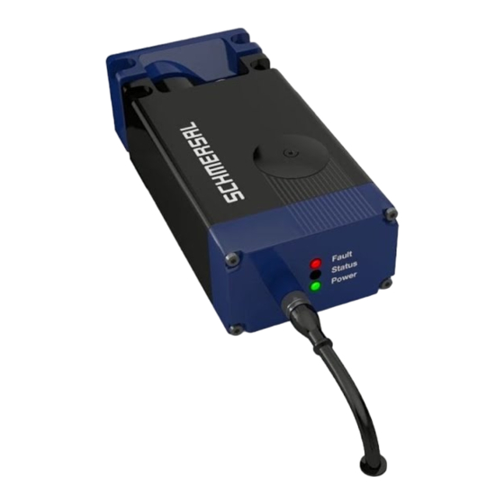
Page 24: Diagnostic Outputs
Arrangement of the LEDs 6.3 Diagnostic outputs The short-circuit proof diagnostic output OUT or OUT1 and OUT2 of the ST2 version can be used for central visualisation or control functions, e.g. in a PLC. I It indicates the switching condition as shown in the table 1. The diagnostic outputs OUT or OUT1 and OUT2 are not safety relevant outputs. - Page 25 Table 1: Diagnostic information of the solenoid interlock AZM400 System Control Safety Diagnostic outputs condition signals outputs Guard locking ST version ST2 version ST2 version green yellow Y1, Y2 function OUT1 OUT2 Door open and Unlock unlocked (bolt retracted) Door closed Unlock Flashes 24 V...
-
Page 26: 调试与维护
Only I2: Unlock Flashes 24 V 24 V Actuator has been taught (Manipulation protection time is running) after 30 min. disabling due to fault see flash code Table 2: Error messages / flash codes red diagnostic LED Flash codes (red) Designation Autonomous Error cause... -
Page 27: Maintenance
4. • Check for a secure installation of the actuator and the solenoid interlock 5. Fitting and integrity of the cable connections. 6. Check the switch enclosure for damages 7. Remove particles of dust and soiling. 8. For versions with emergency exit, the following should also be considered: It should be possible to open the guard system from within the hazardous area;...
Need help?
Do you have a question about the AZM400Z-ST-I1-1P2P-T and is the answer not in the manual?
Questions and answers