Ruijie Reyee RG-AirMetro460G Hardware Installation And Reference Manual
Wireless bridge
Hide thumbs
Also See for Reyee RG-AirMetro460G:
- Hardware installation and reference manual (26 pages) ,
- Configuration manual (103 pages)

Related Manuals for Ruijie Reyee RG-AirMetro460G


Summary of Contents for Ruijie Reyee RG-AirMetro460G
- Page 1 Ruijie Reyee RG-AirMetro460G Wireless Bridge Hardware Installation and Reference Guide Document Version: V1.0 Date: 2024.02.04 Copyright © 2024 Ruijie Networks...
- Page 2 All rights are reserved in this document and this statement. Any reproduction, excerption, backup, modification, transmission, translation or commercial use of this document or any portion of this document, in any form or by any means, without the prior written consent of Ruijie Networks is prohibited.
-
Page 3: Preface
Preface Audience This document is intended for: Network engineers Technical support and servicing engineers Network administrators Technical Support Official website of Ruijie Reyee: https://www.ruijienetworks.com/products/reyee Technical Support Website: https://ruijienetworks.com/support Case Portal: https://www.ruijienetworks.com/support/caseportal Community: https://community.ruijienetworks.com ... - Page 4 Note An alert that contains additional or supplementary information that if not understood or followed will not lead to serious consequences. Specification An alert that contains a description of product or version support. Note This document provides the installation steps, troubleshooting, technical specifications, as well as the specifications and use guidelines of cables and connectors.
-
Page 5: Table Of Contents
Contents Preface ..............................I 1 Product Introduction ........................... 1 1.1 Overview ............................ 1 1.2 Package Contents........................1 1.3 Appearance ..........................2 1.3.1 Appearance ........................2 1.3.2 Ports, Buttons and LEDs ....................3 1.4 Technical Specifications ......................4 1.5 Power Supply Technical Specifications ..................6 1.6 Cooling ............................ - Page 6 3.1 Installation Procedure ......................11 3.2 Before You Begin ........................11 3.3 Safety Precautions During Installation ..................12 3.4 Installing the Wireless Bridge ....................12 3.5 Connecting Cables........................15 3.6 Verifying the Installation ......................16 4 Debugging ............................17 4.1 Setting Up the Configuration Environment ................17 4.2 Checking Environment Before/After Power-on ................
-
Page 7: Product Introduction
Product Introduction Hardware Installation and Reference Guide Product Introduction Overview The RG-AirMetro460G wireless bridge is designed for transmitting surveillance video data or wireless data remotely in scenarios such as tower cranes, factory buildings, campuses, construction sites, and forest fire prevention. It utilizes the IEEE 802.11ac standard for efficient and reliable communication. Operating in the 5 GHz band and supporting 2×2 MIMO technology, this product delivers a maximum wireless rate of 867 Mbps for bridging, ensuring more than sufficient bandwidth for delivering point to point (PTP) and point to multi-point (PTMP) services. -
Page 8: Appearance
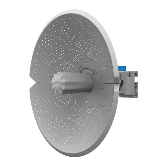
Product Introduction Hardware Installation and Reference Guide Appearance 1.3.1 Appearance Figure 1-1 Appearance of the RG-AirMetro460G Wireless Bridge (Front view) (Back view) -
Page 9: Ports, Buttons And Leds
Product Introduction Hardware Installation and Reference Guide 1.3.2 Ports, Buttons and LEDs Figure 1-2 Ports, Buttons and LEDs of the RG-AirMetro460G Wireless Bridge (Bottom view) Table 1-2 Ports Mark Item Description Ethernet port 10/100/1000 Base-T port, supporting 24 V Passive PoE input Warning Do not use other models of PoE adapters or switches for power supply as it may lead to irreparable damage to the device. -
Page 10: Technical Specifications
Product Introduction Hardware Installation and Reference Guide Mark Item Description Fast blinking (8 to 10 times/second): The device is starting up. Fast blinking (2 times/second): The device is initializing. Fast blinking (2 times/second): The device is upgrading. Off: No port link is established. Solid on: A valid link is established, but the port is not receiving or Port LED sending data. - Page 11 Product Introduction Hardware Installation and Reference Guide 2.4 GHz: 802.11 b/g/n: 2.4000 GHz to 2.483 GHz Operating 5 GHz: 802.11a/n/ac: 5.150 GHz to 5.350 GHz, 5.470 GHz to 5.725 GHz, 5.725 GHz Frequency to 5.850 GHz Bands (Note: Country-specific restrictions apply.) Directional antenna (horizontal 9°...
-
Page 12: Power Supply Technical Specifications
Product Introduction Hardware Installation and Reference Guide Operating temperature: –40℃ to 70℃ (–40° F to +158° F)(excluding the power adapter) (Note: When a power adapter is used, the maximum operating temperature for both the device and the power adapter is 60℃ (140° F).) Environment Storage temperature: –40℃... -
Page 13: Cooling
Product Introduction Hardware Installation and Reference Guide Warning Do not use other models of PoE adapters or switches for supplying power to the network video recorder (NVR) and IP camera (IPC) as it may lead to irreparable damage to these devices. Cooling The RG-AirMetro460G wireless bridge adopts a fanless design. -
Page 14: Preparing For Installation
Preparing for Installation Hardware Installation and Reference Guide Preparing for Installation Safety Precautions Note To prevent device damage and physical injury, please read carefully the safety precautions described in this chapter. The following safety precautions do not cover all possible dangers. 2.1.1 General Safety Precautions ... -
Page 15: Installation Environment Requirements
Preparing for Installation Hardware Installation and Reference Guide Be sure to make a careful check before you shut down the power supply. Do not place the device in a damp/wet location. Do not let any liquid enter the device. ... -
Page 16: Anti-Interference
Preparing for Installation Hardware Installation and Reference Guide 2.2.4 Anti-Interference Keep the device away from the grounding facility or lightning and grounding facility of the power device as much as possible. Keep the device away from high-power radio stations, radar stations, and high-frequency high-current devices. -
Page 17: Installation
Installation Hardware Installation and Reference Guide Installation Caution Before installing the device, make sure that you have carefully read the requirements described in Chapter 2. Installation Procedure Before You Begin Carefully plan and arrange the installation location, networking mode, power supply, and cabling of the device before installation. -
Page 18: Safety Precautions During Installation
Installation Hardware Installation and Reference Guide The installation site meets all requirements described in this guide. The device meets the customers’ requirements. Safety Precautions During Installation You are advised to mount this wireless bridge on a pole with a diameter ranging from 35 mm (1.38 in.) to 89 mm (3.50 in.). - Page 19 Installation Hardware Installation and Reference Guide (3) Attach the antenna mounting bracket to the supporting piece using the long screw and the nut. (4) Attach the wireless bridge to the front of the assembled reflectors. (5) Mount the pole mounting bracket to the pole, and tighten the clamps.
- Page 20 Installation Hardware Installation and Reference Guide (6) Mount the assembled wireless bridge to the pole mounting bracket and tighten the long screw. (7) Properly connect the Ethernet cable, and then install the waterproof cover. The installation is complete.
-
Page 21: Connecting Cables
Installation Hardware Installation and Reference Guide Connecting Cables (1) Use or make an Ethernet cable based on the distance between the wireless bridge and the power source. The device supports PoE power supply over Cat5e or better cables with a cable length up to 100 meters (328 ft.). -
Page 22: Verifying The Installation
Installation Hardware Installation and Reference Guide Figure 3-1 Cable Connection Power socket PoE adapter Camera, switch, PC, etc. Maximum distance of PoE: 100 meters (328 ft.) (Cat5e or better cables) Warning After the Ethernet cable is securely connected to the device, cover the device with a waterproof cover to shield it from potential water and dust damage. -
Page 23: Debugging
Check whether the power supply is properly connected. Scan the QR code on this page or on the device to download the Ruijie Reyee app. Launch the Ruijie Reyee app, click Add a project, and follow the instructions to complete setup. - Page 24 Debugging Hardware Installation and Reference Guide Note A username is not required on your first login. You can enter the initial password “admin” to log in. To ensure device security, change the password after login, and update the password regularly.
-
Page 25: Monitoring And Maintenance
Monitoring and Maintenance Hardware Installation and Reference Guide Monitoring and Maintenance Monitoring You can observe the LED status to monitor the device in operation. Hardware Maintenance If the hardware is faulty, please contact Ruijie Networks technical support for assistance. -
Page 26: Common Troubleshooting
Common Troubleshooting Hardware Installation and Reference Guide Common Troubleshooting Troubleshooting Flowchart... -
Page 27: Appendix
Appendix Hardware Installation and Reference Guide Appendix Connectors and Media 1000BASE-T/100BASE-TX/10BASE-T Port The 1000BASE-T/100BASE-TX/10BASE-T port is a 10/100/1000 Mbps auto-negotiation port that supports auto MDI/MDIX Crossover. Compliant with IEEE 802.3ab, the 1000BASE-T port requires Category 5e 100-ohm UTP or STP (recommended) with a maximum distance of 100 meters (328 feet). - Page 28 Appendix Hardware Installation and Reference Guide The following figure shows feasible connections of the straight-through and crossover twisted pair cables for a 100BASE-TX/10BASE-T port. Figure 7-2 100BASE-TX/10BASE-T Twisted Pair Connections Straight-Through Crossover Switch Adapter Switch Switch...
Need help?
Do you have a question about the Reyee RG-AirMetro460G and is the answer not in the manual?
Questions and answers