
Related Manuals for Ruijie RG-MUX-8LC


Summary of Contents for Ruijie RG-MUX-8LC
- Page 1 Transparent Distribution Device Hardware Installation and Reference Guide Document version: 1.1 Date: July 28, 2023 Copyright © 2023 Ruijie Networks...
- Page 2 Some or all of the products, services or features described in this document may not be within the scope of your purchase or use. Unless otherwise agreed in the contract, Ruijie Networks does not make any express or implied statement or guarantee for the content of this document.
- Page 3 Introduction to the Transparent Distribution Device Preface Intended Audience This document is intended for: Network engineers Technical support and servicing engineers Network administrators Technical Support Ruijie Networks website: https://www.ruijienetworks.com/ Technical support website: https://ruijienetworks.com/support Case portal: https://caseportal.ruijienetworks.com Community: https://community.ruijienetworks.com ...
- Page 4 Hardware Installation and Reference Guide Introduction to the Transparent Distribution Device comment line. Signs The signs used in this document are described as follows: Warning An alert that calls attention to important rules and information that if not understood or followed can result in data loss or equipment damage.
- Page 5 20 nm increments, this series can extend 10G and 1G optical cables to each room when used with Ruijie Simplified Optical Ethernet (SOE) solution. The core switches integrate functions of a combiner, reduce the number of occupied ports on the core side, and support virtual switching unit (VSU) functions.
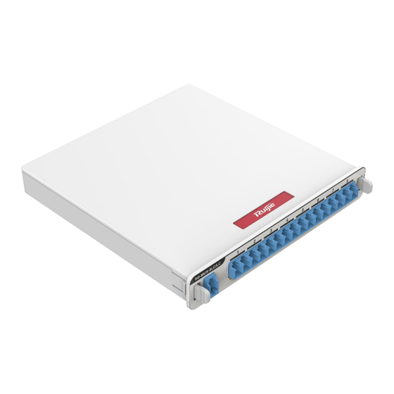
- Page 6 Hardware Installation and Reference Guide Introduction to the Transparent Distribution Device device or optical splitter. Caution The transparent distribution devices must be used with Ruijie CWDM transceivers. 1.1 RG-MUX-8LC/LC 1.1.2 Specifications Table 1-2 Specifications Model RG-MUX-8LC/LC Description 8-port transparent distribution device on the building side. A single port supports 1000M and 10G rates.
- Page 7 5% RH to 95% RH (non-condensing) Standards GR-1221-Core and GR-1209-Core Net Weight < 0.25 kg (0.55 lbs) 1.1.3 Appearance Integrating one group of CWDM 16-wavelength passive demultiplexer, RG-MUX-8LC/LC supports eight access ports and accommodates one input port. Figure 1-2 RG-MUX-8LC/LC Figure 1-3 Front Panel...
- Page 8 Hardware Installation and Reference Guide Introduction to the Transparent Distribution Device Figure 1-4 Rear Panel Figure 1-5 Product Label RG-MUX-8LC/LC-H 1.2.1 Specifications Table 1-3 Specifications Model RG-MUX-8LC/LC-H Description 8-port transparent distribution switch on the building side. A single port supports 1000M and 10G rates.
- Page 9 5% RH to 95% RH (non-condensing) Standard GR-1221-Core and GR-1209-Core Net Weight < 0.25 kg (0.551 lbs) 1.2.2 Appearance Integrating one group of CWDM 16-wavelength passive demultiplexer, RG-MUX-8LC/LC-H supports eight access ports, and has one input port with low insertion loss.
- Page 10 Hardware Installation and Reference Guide Introduction to the Transparent Distribution Device Figure 1-6 RG-MUX-8LC/LC-H Figure 1-7 Front Panel Figure 1-8 Rear Panel...
- Page 11 Hardware Installation and Reference Guide Introduction to the Transparent Distribution Device Figure 1-9 Product Label RG-MUX-EXT 1.3.1 Specifications Table 1-4 Specifications Model RG-MUX-EXT Description Expansion module of the transparent distribution device on the building side, which is also an optical splitter. It supports 2:N dual uplinks and is equipped with patch cables.
- Page 12 Hardware Installation and Reference Guide Introduction to the Transparent Distribution Device Operating 0° C to 55° C (32° F to 131° F, altitude: 0 ft. to 5905.51 ft.) Temperature Storage –40° C to +85° C (–40° F to +185° F) Temperature Operating Humidity 5% RH to 95% RH (non-condensing)
- Page 13 Hardware Installation and Reference Guide Introduction to the Transparent Distribution Device Figure 1-11 Front Panel Figure 1-12 Rear Panel Figure 1-13 Product Label RG-MUX-BOX 1.4.1 Specifications Table 1-5 Specifications Model RG-MUX-BOX Description Chassis for transparent distribution device on the building side...
- Page 14 Hardware Installation and Reference Guide Introduction to the Transparent Distribution Device with six slots, which is fit for 8-port transparent distribution device or splitter. Operating –40° C to +85° C (–40° F to +185° F) Temperature Storage –40° C to +85° C (–40° F to +185° F) Temperature Operating Humidity 5% RH to 95% RH...
- Page 15 Hardware Installation and Reference Guide Introduction to the Transparent Distribution Device Figure 1-15 Front Panel Figure 1-16 Rear Panel Figure 1-17 Product Label CWDM Transceivers Note CWDM transceivers on the core side are used with the corresponding switch, while access CWDM transceivers are used with transparent distribution device and access switch.
- Page 16 Hardware Installation and Reference Guide Introduction to the Transparent Distribution Device The number of access CWDM transceiver module must match the port number of the transparent distribution device. For instance, the CWDM transceiver of Access 1 should be connected to Output Port 1 of the corresponding transparent distribution device. Note The CWDM transceivers (SFG-LR-SM and SFX-LR-SM) on the core side, should be plugged into the core switch in the core equipment room, and be connected to the transparent...
- Page 17 Hardware Installation and Reference Guide Introduction to the Transparent Distribution Device 1.5.3 GE-SFP-LR(A1-8)-H The GE-SFP-LR(A1-8)-H is a group of eight high-power 1G CWDM transceivers on the access side with eight wavelengths and single-mode optical cables. The optical cables are 10 km (6.21 mi.les) long, using LC connector.
- Page 18 Hardware Installation and Reference Guide Introduction to the Transparent Distribution Device 1.5.5 XG-SFP-LR(A1-8)-H The XG-SFP-LR(A1-8)-H is a group of eight high-power 10G CWDM transceivers on the access side, with eight wavelengths and single-mode optical cables. The optical cables are 10 km (6.21 miles) long, using the LC connector.
- Page 19 Hardware Installation and Reference Guide Introduction to the Transparent Distribution Device XG-SFP-LR-SM1511-A5-H Access 5 10 Gbps XG-SFP-LR-SM1531-A6-H Access switch 6 10 Gbps XG-SFP-LR-SM1551-A7-H Access 7 10 Gbps XG-SFP-LR-SM1571-A8-H Access 8 10 Gbps 1.5.7 XG-SFP-LR(A1-8) The XG-SFP-LR(A1-8) is a group of eight low-power 10G CWDM transceivers on the access side, with eight wavelengths and single-mode optical cables.
- Page 20 Hardware Installation and Reference Guide Introduction to the Transparent Distribution Device Series SFP+ Model Number Rate XG-SFP-LR-SM1431-A1 Access 1 10 Gbps XG-SFP-LR-SM1451-A2 Access 2 10 Gbps XG-SFP-LR(A1-4) XG-SFP-LR-SM1471-A3 Access 3 10 Gbps XG-SFP-LR-SM1491-A4 Access 4 10 Gbps...
- Page 21 Hardware Installation and Reference Guide Preparing for Installation Preparing for Installation Safety Precautions Warning To avoid personal injury and device damage, please carefully read the safety precautions before installation. The following safety precautions may not cover all possible hazardous situations. ...
- Page 22 RG-MUX series transparent distribution devices, it is recommended that the aisles of the server room should be no less than 0.8 m (2.62 ft.) wide. Models of transparent distribution device on the building side: RG-MUX-8LC/LC RG-MUX-8LC/LC-H ...
- Page 23 Hardware Installation and Reference Guide Preparing for Installation 2.2.4 Cleanliness Dust poses a major threat to the device. Dust falling on the LC/UPC connectors of the transparent distribution device will cause electrostatic adsorption and contaminate the connector, leading to poor contact. Especially in the case of low indoor relative humidity, electrostatic adsorption is prone to occur, which may affect the service life of the device and cause communication failure.
- Page 24 Hardware Installation and Reference Guide Preparing for Installation Rack Installation Requirements If the RG-MUX series transparent distribution devices are to be installed in a rack, please make sure the rack meets the following requirements. (1) Use a four-post standard 19-inch rack. The distance between square strips on the left and right sides of the standard 19-inch rack is 465 mm (18.31 in.).
- Page 25 Hardware Installation and Reference Guide Preparing for Installation Figure 2-2 Rack Dimensions The guide rails or tray can bear the weight of the transparent distribution device and its accessories. The cabinet has a good ventilation system. The open area of front and rear doors is greater than 50%.
- Page 26 Hardware Installation and Reference Guide Preparing for Installation Note The transparent distribution device does not come with a tool kit. You need to prepare a tool kit by yourself. Fiber Cabling Requirements Before cabling, make sure that the optical connector and the optical cable match the optical interface.
- Page 27 Hardware Installation and Reference Guide Installation Installation RG-MUX series transparent distribution devices must be installed indoors. Caution Before installing the device, make sure that you have carefully read and met the requirements specified in Chapter 2. Checklist Before Installation RG-MUX series transparent distribution devices are complex in device deployment and cabling.
- Page 28 Hardware Installation and Reference Guide Installation (2) You have to prepare the LC fiber patch cable connecting the LC flange output port of the transparent distribution device and the ODF on the building side. Optical cables from each access room are pulled to and fused to the ODF on the building side. (3) If FC or other types of ODF is used during construction, use the patch cable with FC to LC connector to connect with the transparent distribution device.
- Page 29 Hardware Installation and Reference Guide Installation Installation Procedure Install the core switch in the rack Record the access port number of the ODF, room number, and the number of CWDM transceiver connected to the output port Plug in the SFG or SFX transceiver Carry the corresponding CWDM transceiver Connect the SFG or SFX transceiver to the fiber trunk to desired room and plug it into the SOE...
- Page 30 One is to wall-mount the RG-MUX-BOX and then install the transparent distribution device or optical splitter on it. The other is to directly wall-mount the devices with brackets. 1. Wall-Mounting the RG-MUX-8LC/LC Without RG-MUX-BOX as an Example (1) Screw the brackets of RG-MUX-8LC/LC using a screwdriver for wall- mounting, as follows.
- Page 31 Hardware Installation and Reference Guide Installation (2) Put the brackets against the wall and mark the screw hole location of the brackets. Drill holes at the corresponding locations and install M4 wall anchors. The size of the wall anchors is as follows. (3) Secure the transparent aggregation device, with brackets attached, to the M4 wall anchors using the provided screws.
- Page 32 Hardware Installation and Reference Guide Installation Put the brackets against the wall and mark the screw hole location of the brackets. Drill holes at the corresponding locations and install M6 x 50 wall anchors. The size of the wall anchors is as follow. Secure the transparent distribution device onto the wall anchors using the provided screws.
- Page 33 Hardware Installation and Reference Guide Installation 3.4.2 Installing Devices on Building Side and Access Side Installation location: The transparent distribution device can be installed in the ELV room on the building side in a standard 19-inch rack or wall-mounted using mounting brackets. Refer to Chapter 3.3 for installation modes.
- Page 34 Hardware Installation and Reference Guide Installation (3) In Figure xx, push the CWDM transceiver into the optical port of the indoor switch until the CWDM transceiver is in place. (4) Check whether the port of the switch is up. If not, exchange the TX and RX ends of the optical cable.
- Page 35 Hardware Installation and Reference Guide Installation CWDM Output port 8 Access 8 transceiver 8 3.4.3 Mapping Between Numbers of Access CWDM Transceivers and Output Port Numbers of the Transparent Distribution Device Principles: 1. The number of access CWDM transceiver must match the output port number of the transparent distribution device.
- Page 36 Hardware Installation and Reference Guide Installation Bundling Steps (1) Bind the hanging part of the optical cables and twisted pairs, and lead them to the left and right sides of the device. (2) On both sides of the device, secure the optical cables and twisted pairs to the cable management bracket.
- Page 37 Hardware Installation and Reference Guide Troubleshooting Troubleshooting General Procedure 4.1.1 Troubleshooting During Installation Possible Solution Cause The output Match CWDM transceivers with the output ports of the transparent port distribution device according to numbers 1-8 and make connections number of accordingly.
- Page 38 Hardware Installation and Reference Guide Troubleshooting optical cable may occur. To resolve failures caused by poor connection and poor quality of pigtails, fiber-optic end-face cleaning tools and optical power meter should be used for troubleshooting according to the fault symptom. 4.1.2 Troubleshooting After Installation Symptom...
- Page 39 ODF for any anomaly. A crosscheck is recommended. Please refer to Chapter 4.1.3 for details about crosscheck. Note If the problem still persists, please contact Ruijie Networks Technical Support team. 4.1.3 Troubleshooting During Operation by Crosscheck...
- Page 40 Hardware Installation and Reference Guide Troubleshooting same input port can be interrupted, and replace connection of all eight output ports of the input port with another group of functioning output ports of the same device. Or you can replace the device for crosscheck. The connection of the input port and all of its output ports should be replaced.
- Page 41 Hardware Installation and Reference Guide Troubleshooting access over-bent, or contaminated. cable. switches The SFX or SFG transceiver on the core Replace the SFX or SFG connected side is faulty. transceiver on the core side. eight input port transparent Replace transparent output ports of distribution device on the building side distribution device on the...
- Page 42 Hardware Installation and Reference Guide Troubleshooting If the faulty ports are the output ports of an input port on the transparent distribution device, then it is highly likely that the SFX or SFG transceiver, transparent distribution device, or fiber trunk cable are faulty. In this case, first troubleshoot the SFX or SFG transceiver and transparent distribution device.
- Page 43 SFX or SFG transceiver, or transparent distribution device for crosscheck.. The connection of the input port and all of its output ports should be replaced. Perform troubleshooting on both the core side and building side. Note If the problem still persists, please contact Ruijie Networks Technical Support team.
- Page 44 Hardware Installation and Reference Guide Appendix A CWDM Transceivers Appendix A CWDM Transceivers Technical Specifications Caution An optical module is a laser transmitter. Do not look directly into the optical module to prevent it from burning your eyes. To keep the optical module clean, ensure that the unused ports remain capped. ...
- Page 45 Hardware Installation and Reference Guide Appendix A CWDM Transceivers R-SM1551- A7-H GE-SFP-L Access R-SM1571- –1 –22.0 –3.0 A8-H Table 5-2 Cabling Specifications of GE SPF Transceivers Core Connector Cable Max. Cabling Model Specification Type Type Distance (μm) 10 km (6.21 GE-SFP-LR-SM1431-A1-H 9/125 mi.)
- Page 46 Hardware Installation and Reference Guide Appendix A CWDM Transceivers (Yes or No) XG-SFP- LR-SM14 Access 1 –0.5 –15 31-A1 XG-SFP- LR-SM14 Access 2 –0.5 –15 51-A2 XG-SFP- LR-SM14 Access 3 –0.5 –15 71-A3 XG-SFP- LR-SM14 Access 4 –0.5 –15 91-A4 XG-SFP- LR-SM15 Access 5...
- Page 47 Hardware Installation and Reference Guide Appendix A CWDM Transceivers 71-A3-H XG-SFP- LR-SM14 Access 4 –15.5 91-A4-H XG-SFP- LR-SM15 Access 5 –15.5 11-A5-H XG-SFP- LR-SM15 Access 6 –15.5 31-A6-H XG-SFP- LR-SM15 Access 7 –15.5 51-A7-H XG-SFP- LR-SM15 Access 8 –15.5 71-A8-H Table 5-4 Cabling Specifications of 10GE SFP+ Transceivers Core...
- Page 48 Hardware Installation and Reference Guide Appendix A CWDM Transceivers 10 km (6.21 XG-SFP-LR-SM1531-A6 9/125 mi.) 10 km (6.21 XG-SFP-LR-SM1551-A7 9/125 mi.) 10 km (6.21 XG-SFP-LR-SM1571-A8 9/125 mi.) 10 km (6.21 XG-SFP-LR-SM1431-A1-H 9/125 mi.) 10 km (6.21 XG-SFP-LR-SM1451-A2-H 9/125 mi.) 10 km (6.21 XG-SFP-LR-SM1471-A3-H 9/125 mi.)
- Page 49 Hardware Installation and Reference Guide Appendix B Recommended Cabling SFX-L 1271 to 1411 –0.5 –13 R-SM Table 5-6 Cabling Specifications of SFG-LR-SM and SFX-LR-SM Core Connector Cable Max. Cabling SFP Model Specification Type Type Distance (μm) 10 km (6.21 SFG-LR-SM 9/125 mi.) 10 km (6.21...
- Page 50 Hardware Installation and Reference Guide Appendix C Site Selection Appendix C Site Selection The machine room should be at least 5 km (3.11 mi.) away from heavy pollution sources, such as smelter works, coal mine, and thermal power plant. The machine room should be at least 3.7 km (2.3 mi.) away from medium pollution sources, such as chemical factory, rubber factory, and electroplating factory.
- Page 51 Hardware Installation and Reference Guide Appendix C Site Selection that the air conditioner is installed in a location where water droplets from windows or ventilation openings cannot be blown into devices.
Need help?
Do you have a question about the RG-MUX-8LC and is the answer not in the manual?
Questions and answers