
Related Manuals for Ruijie RG-WS6512-L


Summary of Contents for Ruijie RG-WS6512-L
- Page 1 Ruijie RG-WS6512-L Wireless Controller Hardware Installation and Reference Guide Document Version: V1.0 Date: 2023.03.06 Copyright © 2023 Ruijie Networks...
- Page 2 All rights are reserved in this document and this statement. Any reproduction, excerption, backup, modification, transmission, translation or commercial use of this document or any portion of this document, in any form or by any means, without the prior written consent of Ruijie Networks is prohibited.
- Page 3 Preface Intended Audience This document is intended for: Network engineers Technical support and servicing engineers Network administrators Technical Support Ruijie Networks Website: https://www.ruijienetworks.com/ Technical Support Website: https://ruijienetworks.com/support Case Portal: https://caseportal.ruijienetworks.com Community: https://community.ruijienetworks.com ...
-
Page 4: Product Introduction
Product Introduction Overview The RG-WS6512-L high-performance wireless access controller (AC) is developed by Ruijie Networks to support next- generation high-speed wireless networks. It can be deployed on a Layer 2 or Layer 3 network without any architecture or hardware changes, delivering seamless and secure control over wireless networks. The RG-WS6512-L can manage up to 128 wireless access points (APs) by default. -
Page 5: Package Contents
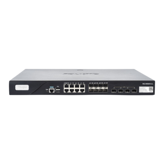
1. System logo LED 6. 1000Base-X SFP combo ports 2. Reset button 7. 10GBASE-SR/LR SFP+ ports 3. RJ45 console port 8. QR code for Ruijie AP and AC initialization guide 4. USB 2.0 port 9. Power modules 5. 10/100/1000Base-T auto-sensing Ethernet ports 10. - Page 6 Hardware Installation and Reference Guide Product Introduction Item Quantity User manual Warranty card and hazardous substance table M4 x 8 mm Philips screw Yellow and green ground cable Console cable Power cord Product LED Indicators Table 1-2 Product LED Indicators Status System logo LED Initializing upon power-on/Upgrading: blinking green...
-
Page 7: Technical Specifications
1.5.1 Dimensions and Weight Table 1-3 Dimensions and Weight Dimensions and RG-WS6512-L Weight Physical Dimensions (W 440 mm × 43.6 mm × 340 mm (17.32 in. × 1.72 in. × 13.39 in) (excluding the foot × D × H) pads) - Page 8 Hardware Installation and Reference Guide Product Introduction Power Supply and RG-WS6512-L Consumption Output Voltage 12V/5.83A Note A combo port consists of an optical port and an electrical port. The optical port and electrical port cannot work at the same time. If one port is enabled, the other is disabled. You can select the port type as required.
- Page 9 Hardware Installation and Reference Guide Product Introduction...
-
Page 10: Power Supply
50 Hz to 60 Hz Rated current 2 A Max. Power cord 10 A power cord Current equalization Supported The RG-WS6512-L adopts AC input and supports power module redundancy. 1.6.2 Power LED Table 1-8 Power LED Status Normal input: steady green... -
Page 11: Preparing For Installation
Preparing for Installation Precautions An AC functions as a transfer station for network connections. Its functionality is related to the normal operation of the entire network. When installing and using the RG-WS6512-L, pay attention to the following safety recommendations: ... -
Page 12: Temperature/Humidity Requirements
Hardware Installation and Reference Guide Preparing for Installation 2.2.1 Temperature/Humidity Requirements To ensure the normal operation and prolonged service life of the device, maintain an appropriate temperature and humidity in the equipment room. If the humidity in the equipment room keeps high for a long time, some mechanical performance issues may occur, such as the poor insulation of insulating materials and even electric leakage. -
Page 13: Anti-Static Requirements
2.2.3 Anti-static Requirements Although the anti-static treatment has been applied to the RG-WS6512-L during the circuit design, strong static electricity will still cause damage to the circuit board. Regarding the communication network connected with the device, static electricity mainly comes from the following two aspects: ... - Page 14 Hardware Installation and Reference Guide Preparing for Installation to install air conditioners in hot areas. The ventilation and heat dissipation of the cabinet and workbench are satisfactory. The cabinet or the workbench is strong enough to support the weight of the device and its accessories. ...
-
Page 15: Installation Procedure
Hardware Installation and Reference Guide Installing the AC Installing the AC Installation Procedure To avoid device damage caused by any improper operation during the installation process, install the device according to the procedure shown in the following figure. Figure 3-1 Installation Procedure Start Preparation: Read Chapter 2 and confirm... -
Page 16: Installing The Power Cord
Do not place heavy objects on the device. Installing the Power Cord The RG-WS6512-L supports AC power supply (100 V to 240 V/50 Hz to 60 Hz) The selected power supply modules must meet the system power requirements. Note For details about the power supply types supported by the device, see Chapter 1. -
Page 17: Verifying The Installation
Users can connect to the console port of the RG-WS6512-L based on the following procedure: Connect one end of the RJ45 serial cable delivered with the RG-WS6512-L to the console port, and the other end to the DB-9 male connector of the microcomputer that is used to configure the AC. -
Page 18: Setting Up The Configuration Environment
Step 1: Connect the serial port of a character terminal or microcomputer to the console port (also called configuration port or control panel port) of the RG-WS6512-L by using a standard RS232 cable. Step 2: Configure the communication parameters of the terminal. If a microcomputer is used, a terminal emulation program, such as the HyperTerminal provided by the Windows operating system, must be running. - Page 19 Figure 4-2 Selecting the Serial Port Figure 4-3 Figure 4-3 Configuring the Communication Parameters of the Serial Port After the environment is set up, the RG-WS6512-L can be powered on. Powering On and Starting the Device Checking Before Power-on Before powering on the RG-WS6512-L, check the following items:...
- Page 20 Check whether the ventilation system is normal. (Method: After the RG-WS6512-L is powered on, you should be able to hear the sound from fan rotating and you can feel the flow of air by placing your hand near the air vents of the RG-WS6512-L.) ...
- Page 21 Note The preceding self-extracting information is used as an example. The actual information varies with different hardware or software versions. If the RG-WS6512-L is used for the first time, it is recommended to configure some basic parameters of the RG-WS6512-L.
-
Page 22: Troubleshooting
Troubleshooting Troubleshooting Power Failures Check the power LED of the power module to determine whether the power system of the RG-WS6512-L fails. For the normal LED status, see Chapter 1. If an exception occurs, perform the following operations: Check whether the power supply switch of the RG-WS6512-L is turned on. - Page 23 Hardware Installation and Reference Guide Troubleshooting The serial port is incorrectly Check whether the serial port is configured. configured based on the required parameter settings for the serial port. Frame RX/TX errors or The twisted pair cable is faulty. Replace the twisted pair cable. connection failures of The cable length exceeds 100 Check the port configuration and...
Need help?
Do you have a question about the RG-WS6512-L and is the answer not in the manual?
Questions and answers